Guy and Seth on Simulink

June 14th, 2010

For Each Subsystem and Code Generation

Today Guy Rouleau is back to introduce the code generated from the For Each Subsystem.

Code generator, Guy Rouleau

I created an example model implementing the same functionality as in my previous post, but using Stateflow. I like using Stateflow to create behavioral models when I am most interested in expressing the input-output relationship of the system.

Modulo-4 Counter Using Stateflow

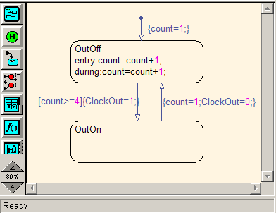
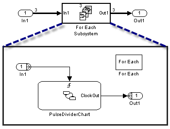
I placed the chart in a For Each Subsystem.

Stateflow chart inside a For Each Subsystem

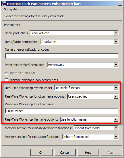
To make the code clearer for this post, I configured the Stateflow chart to generate a Reusable Function in a separate file.

Configuring the Stateflow chart to be a reusable subsystem

Let's now look at the generated code:

Copying the inputs into a contiguous vector
Click image to enlarge.

I added colors to highlight the different parts of the code. In the first part (green), notice that the components of the input signal are placed in contiguous locations in memory. The For Each Subsystem needs this step if the input is not already contiguous. Note that this step respects the optimization settings like Loop unrolling threshold and Use memcpy for vector assignment

Inside the FOR loop, a set of structures are used to store signals and states required by each instance of the subsystem. These structures are passed to the reusable Stateflow chart function. When the loop is completed, each element of the output signal is assigned to its destination.

Reusable Code

As pointed out by my colleague Parasar Kodati, the For Each Subsystem can generate reusable code. Let's say I have multiple instances of this same For Each Subsystem in a model, all with a different number of iterations.

Multiple instances of For Each Subsystems

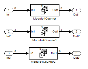
I configure all the For Each Subsystems to generate a reusable function with the same function name and file name. Now the FOR loop is located in a separate function, which take as input the number of iterations.

Multiple instances of For Each Subsystems
Click image to enlarge.

Notice that I used different vector lengths to highlight how the inputs and outputs to the For Each Subsystem are handled by the Loop unrolling threshold and Use memcpy for vector assignment options.

Now it's your turn

Are you already using the For Each subsystem? Leave a comment here and tell us what you are using it for.

3 Responses to “For Each Subsystem and Code Generation”

  1. wei replied on :

    @Guy, I don’t have 2010a yet. Would you highlight the difference in these two functions, PulseDivider() and ModuloCounter(), between For-each coegen and standard codegen versions? Could code be shared as attachment to this post?

    Thank You.

  2. Simone Leon replied on :

    At present I am working on a Simulation Model containing 2 subsystems in Matlab Simulink:
    • Subsystem A – generates some data
    • Subsystem B – reads the generated data from the workspace

    Right now each subsystem is in a different Simulink file. I would run Subsystem A first. This data would be saved to the workspace and then I would run Subsystem B which reads the data from the workspace.

    I would like to put these two models together in one simulation window. However the problem is that each model runs at a different simulation time. And in order to read the data form the workspace the first simulation must first stop and the variables sent to the workspace.

    Is there any way to stop the simulation for the Subsystem A, therefore sending the variables to the workspace. And then Subsystem B would be executed to read from the workspace.

    I tried using the trigger and enable blocks but because the simulation does not stop and send the variables to the workspace before Subsystem B is activated, Subsystem B is unable to read the data generated by Subsystem A. I have done some research and it shows that simulation must stop in order to be able to read from the workspace.

    Is it therefore possible to have these two subsystems in one file sharing the same space? I would like Subsystem A simulation to start and stop, therefore sending the variable to the workspace and Subsystem B is activated automatically after the variables were sent to the workspace.

    Please remember that:
    • Subsystem B needs the variables generated by Subsystem A
    • Subsystem B reads from the workspace
    • Both subsystems have different simulation stop times
    • Subsystem A must stop first in order to send the variables the workspace

    Thank you for any assistance.

  3. hein replied on :

    % please look my for loop! Can i use For Each Subsystem for my problem in simulation?
    clc
    clear
    Nc=264;
    W=7500;
    dt=0.00014;
    H=350000;
    da=0.7;
    lz=20;
    wavelength1=0.008333;
    nx1=2*floor((H*tan(wavelength1/(2*da))/lz));
    ny1=2*floor((H*tan(wavelength1/(2*da))/lz));
    thida1=wavelength1/da;
    b=(2*pi*W^2)/(H*wavelength1);
    asha=sqrt(0.0056);
    d=1;
    k1=0.866*da/(Nc*d);
    TDeff2=asha^2*thida1^2/(5.5*asha^2*(1+k1)+thida1^2);
    a=W^2/(2*H^2*TDeff2);
    aa1=normrnd(0,1,nx1+1,ny1+1);
    for k=0:1:Nc-1
    for i=0:1:nx1
    for j=0:1:ny1
    h1(j+1,i+1)=aa1(i+1,j+1);
    x(j+1,i+1)=lz*i;
    y(j+1,i+1)=lz*j;
    beta1(j+1,i+1)=tan(sqrt((x(j+1,i+1)+y(j+1,i+1))/(H*h1(j+1,i+1))));
    R0(j+1,i+1)=sqrt(H^2+y(j+1,i+1).^2);
    b1(i+1,j+1)=b./(sqrt((1+y(j+1,i+1).^2)./H^2));
    Uc1(i+1,j+1,k+1)=exp(-a.*(k.*dt-x(j+1,i+1)./W).^2).*exp(-y(j+1,i+1).^2./(2*H^2*TDeff2)).*cos(-b1(i+1,j+1).*(k.*dt-x(j+1,i+1)./W).^2-(4*pi*R0(j+1,i+1)/wavelength1)+(4*pi*h1(j+1,i+1)*cos(beta1(j+1,i+1))/wavelength1));
    Us1(i+1,j+1,k+1)=exp(-a.*(k.*dt-x(j+1,i+1)./W).^2).*exp(-y(j+1,i+1).^2./(2*H^2*TDeff2)).*sin(-b1(i+1,j+1).*(k.*dt-x(j+1,i+1)./W).^2-(4*pi*R0(j+1,i+1)/wavelength1)+(4*pi*h1(j+1,i+1)*cos(beta1(j+1,i+1))/wavelength1));
    end
    end
    end

Leave a Reply

Wrap code fragments inside <pre> tags, like this:

<pre class="code">
a = magic(3);
sum(a)
</pre>

If you have a "<" character in your code, either follow it with a space or replace it with "&lt;" (including the semicolon).


MathWorks
Guy Rouleau and Seth Popinchalk are Application Engineers for MathWorks. They write here about Simulink and other MathWorks tools used in Model-Based Design.

These postings are the author's and don't necessarily represent the opinions of The MathWorks.