Guy and Seth on Simulink
February 1st, 2011
Wrong Answers and Gimbal Lock
By Guy Rouleau
I received a request last week where the code generated using Real-time Workshop was giving different answers from the original simulation. This type of requests is the one that scares me the most, because the goal of Real-Time Workshop is to generate a code equivalent to a Simulink model.
Let's see how I approached this challenge!
1. Reproducing the issue
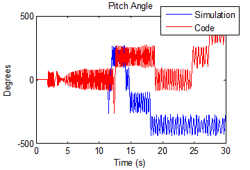
The first thing I do when I have a “different results” case is to confirm what the user reports. I built the model using the GRT target and compared the logged data. They are different!

2. Understanding the system
The model had an architecture similar to the NASA HL-20 demo shipping with the Aerospace Blockset.
My mental representation of this model looks like:

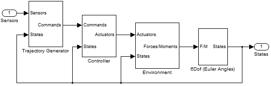
This architecture is used in many domains where the motion of a body in space must be simulated, for example robotics and aerospace.
3. Understanding the results
Let’s take a closer look at the different data and zoom on where they diverge:

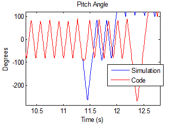
This signal represents an orientation oscillating between +90 and -90 degrees and we see that there is a clear switch around -90 degrees.
4. Guessing something
This is when Seth passed by my office. Based on the indices we had, he suggested that the model might be very sensitive to numerical perturbations. It is well known that floating point round off can cause small differences on the order of eps between generated code and simulation. But when a system is very sensitive and unstable, a difference even as small as eps can grow into completely different results.
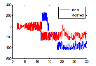
5. Testing the hypothesis
If the model is sensitive to numerical perturbations, modifying the initial states by a random value on the order of eps will affect the results significantly. I tested it, and it changes the simulation results significantly. What I notice is that every time I run the simulation using a new random value, the “switch” around 90 degrees happens at different times.

6. Finding a solution
Now that we know that the model is numerically sensitive, it would be great to fix it!
Having generated six degrees of freedom trajectories for robotic manipulators in the past, I remembered learning somewhere that the Euler angles representation of orientations has a singularity, known as the gimbal lock.
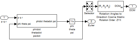
In the 6Dof Euler Angles block, the angles are obtained through integration of the Euler Angles derivative, which is computed using this equation:

where [p q r]T is the body-fixed angular velocity vector and is the the rate of change of the Euler angles. In this equation, when theta is close to 90 degrees the matrix becomes badly scaled and causes the numerical sensitivity described above.
An alternative to integrate the body motion is to compute the rate of change of rotation quaternions instead. :

Quaternions have a lot of advantages: They are numerically more stable than rotation matrices and avoid the gimbal lock problem of Euler angles.
7. Validate your solution
In the Simulink model I replaced the Euler Angles implementation:

by the quaternion representation:

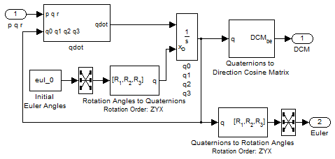
I tested the solution by comparing simulation with numerical perturbation and generated code. Now simulation results and generated code results are matching as expected!
Now it’s your turn!
What is your process of investigation when Simulink does not give the results you expect? Leave a comment here
By
Guy Rouleau
20:00 UTC |
Posted in Analysis, Debugging, Numerics, Simulink Tips |
Permalink |
6 Comments »
You can follow any responses to this entry through the RSS 2.0 feed.
You can skip to the end and leave a response. Pinging is currently not allowed.
Leave a Reply
|
@Guy, Fascinating story! A few things may worth another blog: How to unlock many capabilities Simulink has and complement it with MATLAB is a key in gaining efficiency in MBD.
For example, what’s choice of solver here? A good way to bring rtw code back for comparison simulation? Post-simulation analysis (you are not using Simulink’s scope)? Initial state perturbation setup, …
Good story. People should be taught early on that integrating Euler angle rates is only useful for simulations that need to be linearized where you want to recover the “classical” eigenvalues and eigenvectors; they should NEVER be used for serious time domain work. A couple of quibbles, though:
First, I love quaternions, but they are potentially a bit more computationally intensive than integrating direction cosine matrix rates. Both quaternions and DCM implementations need to be normalized every so often (although quaternion normalization is easier than DCM normalization). But the big advantage of DCMs is that you get what you want – the direction cosine matrix – directly instead of having to convert the quaternion into a DCM. All in all, if you have an application where you need to save every last cycle, integrating the DCM is a bit more efficient. Note that the DCM has some redundancy – only six of the nine elements are independent.
One way to get the best of both worlds is to use quaternions for your more rapidly changing rotational states and DCM for the slower dynamics. In navigation systems, it is not uncommon to integrate quaternion rates to keep track of vehicle attitude, but integrate the DCM directly to keep track of position on the Earth.
Anyway, good article!
@Wei, Thanks for comment. We will definitely look into follow up posts to go deeper into the verification of generated code
@KMR, thank you for the additional details on the many ways to represent orientation. I agree with you, each implementation has its advantages and the important is to use the one appropriate for your problem.
Guy, we recently came across a case where an model gave different results in accelerated mode than it did when run in Normal mode. Disturbing to say the least.
When we removed optimization settings (such as Block Reduction, Conditional input branch execution and Signal storage reuse) the two models agreed. Any insight into why this might be the case?
@ A. Binderman, Accelerator mode uses code generation to run the model. There could be multiple causes for generated code to give results different from normal mode. This post illustrates one. This other post illustrates another:
http://blogs.mathworks.com/seth/?p=129
As you can see in this last post, if there is a control loop in the model, the first thing I do is typically to open the loop. This avoids the propagation and amplification of a small error by the loop. Once this is done, I try to isolate the origin of the difference. I usually do that by logging different signals, based on my knowledge of the model.
I recommend contacting technical support if you need assistance to explain the cause of the difference.
Hi
I have had this error signal from Simulink:
“Only ‘double’ signals are accepted by block type TransportDelay. The signals at the ports of ‘DCtoDC5Kw/Transport Delay’ are of data type ‘uint8,”
How can I get a block that generates double signals so that they can be accepted by the TransportDelay.
I have been looking at few articles and Simulink help, and the closest I got to solve this was
“This class enables you to create workspace objects that you can use to assign or validate the attributes of a signal or discrete state, such as its data type, numeric type, dimensions, and so on. You can create a Simulink”
Is this the right way to get about this problem? or is there another way?
Could you please help with this and your help is much appreciated.
Kind regards
Mohamed Eljarh