Guy and Seth on Simulink
July 25th, 2011
Are you using the right block?
Working in technical support, I receive a lot of models. Sometimes I am impressed by very clever implementations, but sometimes the only thing coming to my mind is "Why is he doing that?". Here are a few examples I want to share with you.
What time is it?
At least once per month, I receive a model where the To Workspace block is used to record the simulation time from a Clock block:

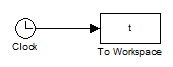
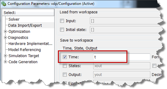
It is not necessary to add blocks to your model. Instead, open the simulation Configuration Parameter and go to the Data Import/Export pane.

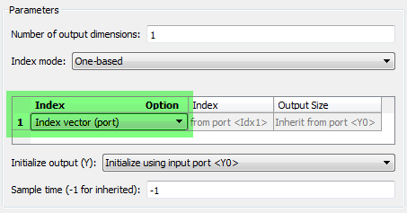
Abusing the MATLAB Function block
I saw this construct in a model recently:

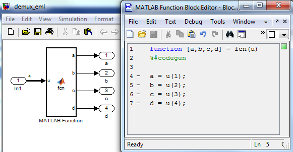
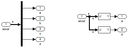
Yes... this works. But using the MATLAB Function block for a task that a basic block can do makes your life more complicated than it should be. In this case, I recommend using the Demux block if you want to extract all the elements of the vector and Selector blocks if you only want a subset. It is faster to setup and does not require code generation when you hit play.
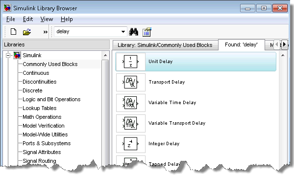
How do you Delay?
When searching for a block to delay a signal, here is what you find:

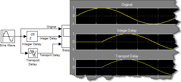
Which one do you pick? At first look, the Integer Delay block and the Transport Delay block might seem to give similar results:

However, when enabling the sample time colors and looking a bit closer at the results, you quickly notice that the Integer Delay block is discrete, while the Transport Delay is continuous.

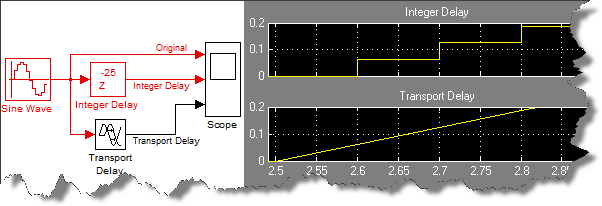
Make sure you use the right block for your situation. The Integer Delay should be used for discrete signals, and the Transport Delay for continuous signals.
Now it's your turn
Do you encounter situations where you are not sure if you are using the right block? Have you ever been told you were using the wrong block? Please share with us by leaving a comment here.
By
Guy Rouleau
19:45 UTC |
Posted in Simulink Tips, Standards and Guidelines |
Permalink |
9 Comments »
You can follow any responses to this entry through the RSS 2.0 feed.
You can skip to the end and leave a response. Pinging is currently not allowed.
Leave a Reply
|
Interesting. In programming language, there are two schools of thoughts.
1) There is one and preferably only one way to implement it. (Examples include Python.)
2) There are more than one ways to implement it. (Examples include Perl and Ruby.)
Shall the users assume that as a graphical modeling language Simulink is in the first category?
Hi Zhi,
This is a good comment. I often say that in Simulink there are always multiple ways to implement a functionality, and the examples above illustrate that.
Based on my experience, you should choose your implementation based on your goal.
In the examples above, I tried to pick situations where, as far as I know, one implementation is always better, whatever your goal is.
However in many cases this is not always that clear. Your goal will determine the best implementation. Example goals could be:
- Clarity of the model: If the model is going to be shared by many engineers for many years, it is important to have good styleguides. In that context, the preffered implementation is the one respecting the styleguides.
- Do you need to generate code or not? If you plan to generate code, your options are restricted to the ones supporting code generation.
- Get a working model as fast as possible: If this is a simple model that you plan to use only once, use whatever does the job. Depending on what you are the most familiar with, you can obtain similar results using Stateflow, or the MATLAB Function block, or different combinations of basic blocks, etc.
I have seen this type of thing more often than I’d like to admit. I finally came up with a set of “Guiding Principles” for modeling. First and foremost is “Simulate the intended functionality” – if it doesn’t work in a simulation, we don’t have any use for it. Following that is “Clearly show the intended functionality” – your examples violate that. These two principles leverage two key advantages of modeling – simulation and clarity. Both should be pursued aggressively.
@Jim, thank you for sharing. I agree that “Simulate the intended functionality” and “Clearly show the intended functionality” are two important guiding principles.
I am currently working on a follow up post on model clarity.
I am relatively new to Simulink. I am usually questioning if I am using the blocks the way they were intended to be used, and whether or not my resulting model can be best implemented using different blocks. Is there a place where I can find samples of commonly used basic constructs or a section of modeling best practices to which you could refer me? – Thanks.
I have seen people making their custom PID controller block rather than just using the library PID controller block which is available in newer versions of MATLAB. I guess some people are so accustomed to designing their own PID controller block, they just don’t know one is already in the library now.
@Pat: Demo models in Simulink are a good place to start. They show examples of valid implementations (generally). There are modeling guidelines for controller development, and some go into very specific details about how to configure certain blocks. Another thing you can use to check your model is Model Advisor. There are some checks that provide block specific advice. Good luck!
I wish to substract 2 signal,every one of them show me 3 diferent
curvs, the signals are coming from a bus selector, how do i work it?
what blocks should I use? -thanks
@Carlu – To substract signal, you usually use the Subtract block… hewever I feel like I am missing something of your situation.
I recommend making your question more complete and posting it on MATLAB Answer.
http://www.mathworks.com/matlabcentral/answers/