Deep Learning in Simulink. Simulating AI within large complex systems
This post is from guest blogger Kishen Mahadevan, Product Marketing. Kishen helps customers understand AI, deep learning and reinforcement learning concepts and technologies. In this post, Kishen explains how deep learning can be integrated into an engineering system designed in Simulink.

 Figure 1: Integrating deep learning models into Simulink
In this blog, we will focus on an example that illustrates the use of deep learning for algorithm development. The example shows how you can integrate a trained deep learning model into Simulink for system-level simulation and code generation.
Note: The features and capabilities showcased in this blog can be applied for algorithm development as well as reduced-order modeling.
 Figure 2: Data for training the deep learning network (top), deep learning network inputs and output (bottom)
With this data, the deep learning model is configured to receive five inputs and provide state-of-charge (SOC) of the battery as the predicted output.
Once the data has been preprocessed, you can train a deep learning model using Deep Learning Toolbox. Sometimes you might already have an AI model developed in TensorFlow or other deep learning frameworks. Using Deep Learning Toolbox you can import these models into MATLAB for system-level simulation and code generation. In this example, we use the existing deep learning model that has been trained in TensorFlow.
 Figure 3: Deep learning workflow
Figure 4: Direct network import from TensorFlow into MATLAB
We then analyze the imported network architecture using analyzeNetwork to check for warning or errors and observe that all the imported layers are supported.
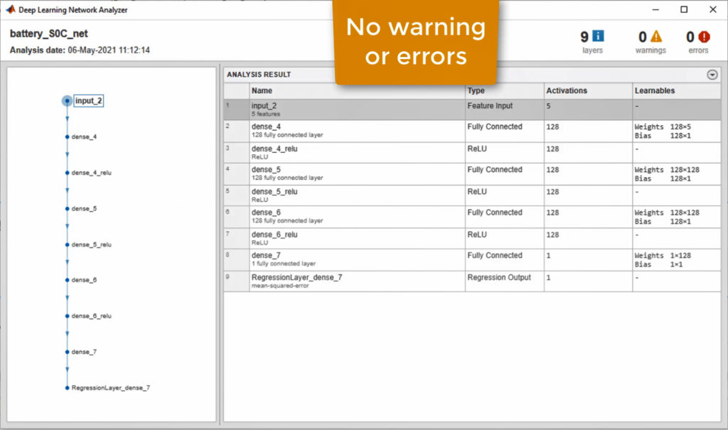 Figure 5: Analyzing the imported network using Deep Learning Network Analyzer
We then load the test data and verify performance of the imported network in MATLAB.
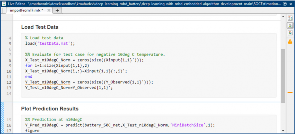 Figure 6: MATLAB code to load and plot prediction results
 Figure 7: Comparing deep learning SOC prediction with true observed SOC value.
We see that the deep learning predicted SOC of the battery is in alignment with the experimentally observed values.
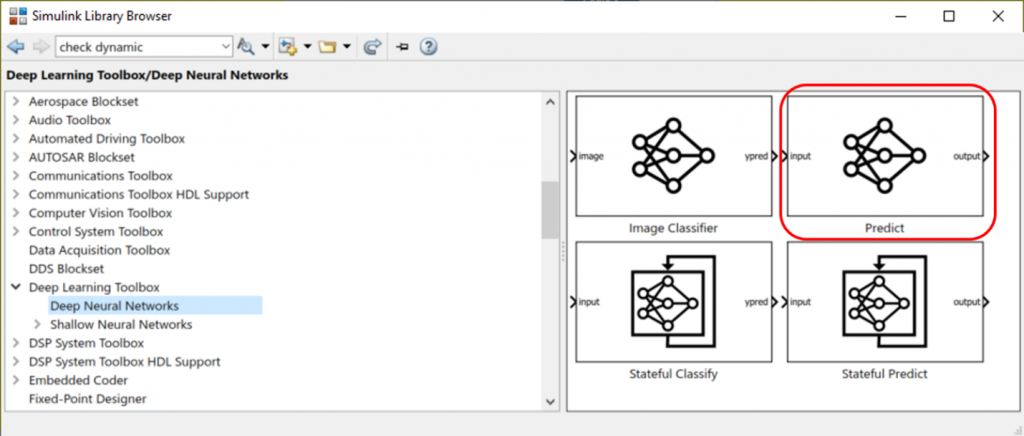 Figure 8: Deep Learning Toolbox library to bring trained deep learning models into Simulink
Figure 9 shows the open-loop Simulink model. The Predict block loads our trained deep learning model into Simulink from a .MAT file. The block receives the preprocessed data as the input and estimates SOC of the battery.
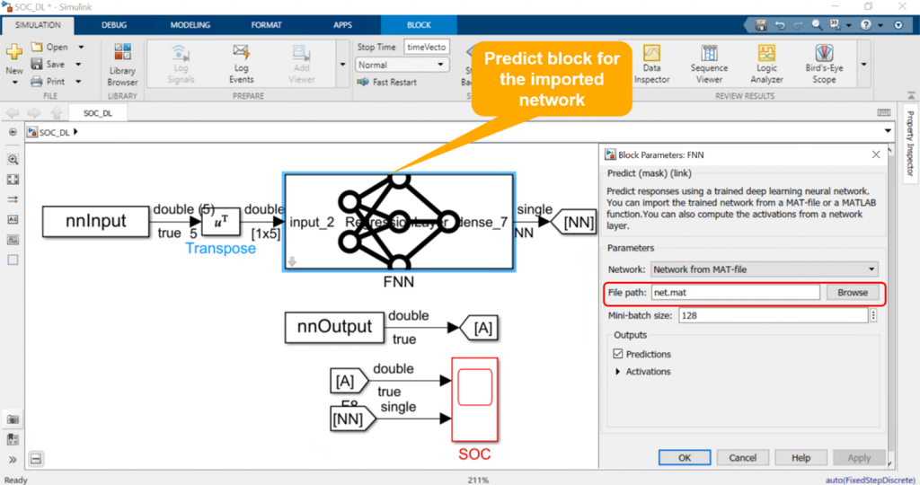 Figure 9: Integrating trained deep learning model into Simulink
We then simulate this model and observe that prediction from our deep learning network in Simulink is identical to the true measured data as shown in Figure 10.
 Figure 10: Simulation result comparing SOC prediction from deep learning network and the true value
Now that we have tested the component in Simulink, we can integrate it into a larger model and simulate the complete system. This is shown in Figure 11.
 Figure 11: System-level Simulink model of a battery management system and a battery plant
Simulink model shown in Figure 11 contains a Battery Management System that is responsible for monitoring battery state and ensuring safe operation, and a battery plant that models the dynamics of a battery and a load.
Our deep learning SOC predictor resides as one of the components under the battery management system along with the logic for cell balancing, prevention of overcharging and over-discharging, and other components.
 Figure 12: Components of battery management system
We now simulate this closed-loop system and observe the SOC predictions.
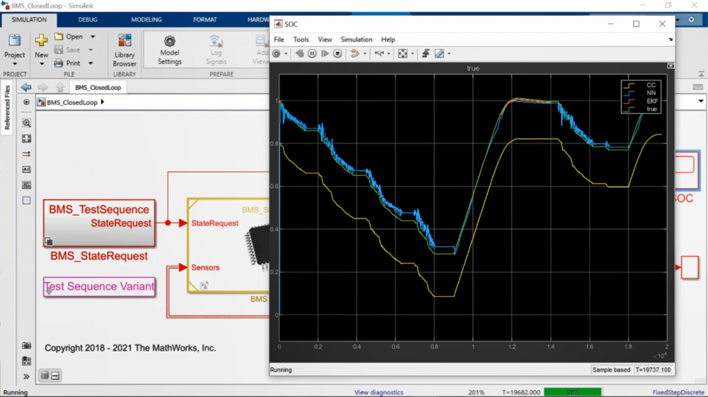 Figure 13: System-level simulation results comparing SOC prediction from deep learning network with the true value
We can see that SOC predictions from our deep learning model is very similar to predictions from the true measured value.
 Figure 14: C code generation for the deep learning network in Simulink
We can see that the generated code contains calls to deep learning step functions that perform SOC prediction.
Next, we deploy the generated code to an NXP board for processor-in-the-loop (PIL) simulation. In PIL simulation, we generate production code only for the algorithm we are developing, in this case the deep learning SOC component, and execute that on the target hardware board, NXP S32K3. This allows us to verify the code behavior on the embedded target.
We now add driver blocks to the model to allow us to interface to and from the NXP board and simulate the model.
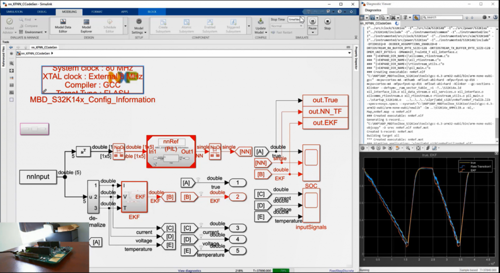 Figure 15: Processor-in-the-loop simulation of deep learning SOC component on NXP board
We see that the behavior of the generated code on the NXP target is identical to the true measured SOC value.

Background
Deep learning is a key technology driving the Artificial Intelligence (AI) megatrend. Popular applications of deep learning include autonomous driving, speech recognition, and defect detection. When deep learning is used in complex systems it is important to note that a trained deep learning model is only a small component of a larger system. For example, embedded software for self-driving cars has components such as adaptive cruise control, lane keep assist, sensor fusion, and lidar processing in addition to a deep learning model that performs a specific task, say lane detection. How do you then integrate, implement, and test all these different components together while minimizing expensive testing with the actual vehicle? This is where Model-Based Design with MATLAB and Simulink fits in.Introduction
When you create a Simulink model for any complex system, you typically have two main components, as shown in Figure 1. The first component represents a collection of algorithms that will be implemented in the embedded system and includes controls, computer vision, and sensor fusion. The second component represents the dynamics of the machine or process we want to develop embedded software for. This component can be a vehicle dynamics model, dynamics of Li-Ion battery, or a model of a hydraulic valve. Having both of these components in the same Simulink model allows you to run simulations to verify and validate embedded algorithms before implementing them on target hardware. Trained deep learning models can be used in both of these components. Examples of using deep learning for algorithm development include use of deep learning for object detection and for soft, or virtual sensing. In the latter scenario deep learning model is used to compute a signal that cannot be measured directly, for example a state-of-charge for a Li-Ion battery. Deep learning models can also be used for environment modeling. This is sometimes referred to as reduced order modeling. Detailed, high-fidelity model of the machine or a process can be replaced with a faster AI-based model that is trained to capture the essential dynamics of the original model. Figure 1: Integrating deep learning models into Simulink
In this blog, we will focus on an example that illustrates the use of deep learning for algorithm development. The example shows how you can integrate a trained deep learning model into Simulink for system-level simulation and code generation.
Note: The features and capabilities showcased in this blog can be applied for algorithm development as well as reduced-order modeling.
Deep Learning in Simulink example
Deep learning workflow involves four main stages:- Data preparation
- AI modeling
- Simulation and Testing
- Deployment
 Figure 2: Data for training the deep learning network (top), deep learning network inputs and output (bottom)
With this data, the deep learning model is configured to receive five inputs and provide state-of-charge (SOC) of the battery as the predicted output.
Once the data has been preprocessed, you can train a deep learning model using Deep Learning Toolbox. Sometimes you might already have an AI model developed in TensorFlow or other deep learning frameworks. Using Deep Learning Toolbox you can import these models into MATLAB for system-level simulation and code generation. In this example, we use the existing deep learning model that has been trained in TensorFlow.
 Figure 3: Deep learning workflow
Step 1: Data Preparation
For this step of the workflow we use the already available preprocessed experiment data collected from a lab. This data includes all the predictors and response as highlighted in Figure 2.This data was provided to us by McMaster University (data Source).Step 2: AI Modeling
As pointed out earlier, the deep learning model can be trained in MATLAB using Deep Learning Toolbox. Refer to the learn more about how to train a deep learning network to predict SOC in MATLAB. As already mentioned in this example we have been provided with a deep learning model that has already been trained in TensorFlow. To import this trained network into MATLAB, we use the importTensorFlowNetwork function. Figure 5: Analyzing the imported network using Deep Learning Network Analyzer
We then load the test data and verify performance of the imported network in MATLAB.
 Figure 6: MATLAB code to load and plot prediction results
 Figure 7: Comparing deep learning SOC prediction with true observed SOC value.
We see that the deep learning predicted SOC of the battery is in alignment with the experimentally observed values.
Step 3: Simulation and Test
To be able to simulate and test this deep learning SOC estimator with all other components of a Battery Management System, we first need to bring this component into Simulink. To accomplish this, we use Predict block from Deep Learning Toolbox block library to add the deep learning model into a Simulink model. Figure 8: Deep Learning Toolbox library to bring trained deep learning models into Simulink
Figure 9 shows the open-loop Simulink model. The Predict block loads our trained deep learning model into Simulink from a .MAT file. The block receives the preprocessed data as the input and estimates SOC of the battery.
 Figure 9: Integrating trained deep learning model into Simulink
We then simulate this model and observe that prediction from our deep learning network in Simulink is identical to the true measured data as shown in Figure 10.
 Figure 10: Simulation result comparing SOC prediction from deep learning network and the true value
Now that we have tested the component in Simulink, we can integrate it into a larger model and simulate the complete system. This is shown in Figure 11.
 Figure 11: System-level Simulink model of a battery management system and a battery plant
Simulink model shown in Figure 11 contains a Battery Management System that is responsible for monitoring battery state and ensuring safe operation, and a battery plant that models the dynamics of a battery and a load.
Our deep learning SOC predictor resides as one of the components under the battery management system along with the logic for cell balancing, prevention of overcharging and over-discharging, and other components.
 Figure 12: Components of battery management system
We now simulate this closed-loop system and observe the SOC predictions.
 Figure 13: System-level simulation results comparing SOC prediction from deep learning network with the true value
We can see that SOC predictions from our deep learning model is very similar to predictions from the true measured value.
Step 4: Deployment
To highlight the capability of deploying our deep learning network in this example, we use the open-loop model that contains just the deep learning SOC predictor. The workflow steps, however, remain the same for the system-level model. We first generate C code from the trained deep learning model in Simulink. Figure 14: C code generation for the deep learning network in Simulink
We can see that the generated code contains calls to deep learning step functions that perform SOC prediction.
Next, we deploy the generated code to an NXP board for processor-in-the-loop (PIL) simulation. In PIL simulation, we generate production code only for the algorithm we are developing, in this case the deep learning SOC component, and execute that on the target hardware board, NXP S32K3. This allows us to verify the code behavior on the embedded target.
We now add driver blocks to the model to allow us to interface to and from the NXP board and simulate the model.
 Figure 15: Processor-in-the-loop simulation of deep learning SOC component on NXP board
We see that the behavior of the generated code on the NXP target is identical to the true measured SOC value.
Key takeaways
- Integrate deep learning models into system-level Simulink models
- Test system-level performance of the design with a deep learning
- Generate code and deploy your application, including deep learning component, to embedded target
- Train deep learning models in MATLAB or import pretrained TensorFlow and ONNX models
Resources to learn more
- Category:
- Deep Learning


Comments
To leave a comment, please click here to sign in to your MathWorks Account or create a new one.