
Building Confidence Before Deployment: Our V-Model Development Process
Guest blogger: Kevin Truyaert
Kevin is project lead of autonomous systems at Vintecc. In this post, he shares how Vintecc uses Model-Based Design and automated testing in its machine-development workflow.
Introduction
The complexity of modern machines is increasing rapidly. Mechanical, electrical, and software components are becoming more tightly connected, making it harder to maintain a complete overview of the system during development. At the same time, software is taking on a growing role in defining machine behaviour, which means that even small software errors can have a significant impact on the final product.
For OEMs developing advanced machines, discovering these errors late in the process can be expensive. A problem found during system integration, commissioning, or on the physical machine often requires changes across multiple development stages and can significantly delay a project.
In practice, development teams often experience the same situation: the focus shifts from building new functionality to solving urgent issues that could have been detected earlier. While delivering a product quickly is important, reducing development time does not only depend on writing code faster. It also depends on creating a development process where problems are identified at the right moment, when they are still manageable.
This is where a structured approach such as the V-model provides value.
Before we walk through how the model works, it is worth showing what it looks like on a real project.
At Vintecc, we turn this kind of engineering into working industrial systems. We are a technology powerhouse for industrial intelligence, the engineering partner that machine builders and manufacturers call when the problem no longer fits in a single discipline. Mechatronics is where it starts: modelling, simulation and control design that let us prove a machine’s behaviour long before the first bolt is turned. From there we keep going: embedded and control software, computer vision, industrial data infrastructure and AI, because a modern machine is no longer mechanics with some code on top. It is one system, and it has to be engineered as one.
Method in action
One of our engineering teams maintains a single control software codebase that runs across multiple successive generations of a customer’s machine and, with small configuration changes, several different device types built on that same platform. One of the challenges in this process is that a change made for one product line cannot be allowed to quietly break another. The software is built using Model-Based Design: it is fully modelled in Simulink and automatically translated to C, so every device variant is built from the same verified source instead of diverging codebases maintained by hand. An automated test suite covering unit, integration, and system level runs against all of it continuously, and model complexity is tracked over time to keep a codebase built to last ten to fifteen years from becoming unmanageable.
Figure 1 shows the results of a test run we perform before we release a new version of the software for one of our customers. It indicates that all tests here came back clean and the release of the current version of the code can go through. Whenever one of these tests, which incorporates both regression and new tests, contains errors, it is necessary to indicate whether the error originates from a bug in the software, or in the test. The latter errors can for example arise when part of the existing behaviour is wished to be updated, the code is altered correctly, however existing tests have not yet been updated and still wish to observe the old behaviour. By combining unit, integrated and system testing on our software stack, we ensure that core features, intermodule links and full system features remain reliable when our software enters the deployment stage for acceptance testing, as bugs are already solved before that stage.
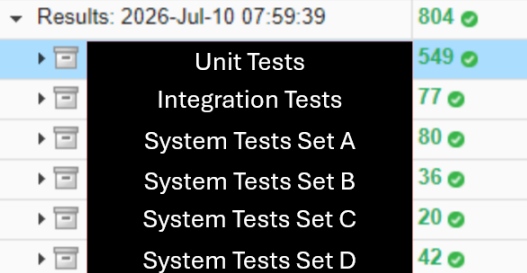
Figure 1: Example of a real customer test suite, continuously updated to ongoing releases, to test the reliability of the software component before actual acceptance testing is performed. Project details have been redacted.
Through this way of working, the latest releases were free of software bugs throughout the acceptance testing phase. A software update, from our end to full deployment on the device, can often take from an hour to half a day, so fixing errors before our delivery can be critical, especially as finding bugs is often a sequential rather than parallel process.
The rest of this post explains the process that makes this possible: the V-model we follow, and how we implement it inside the MATLAB environment.
V-model
By starting from clear system requirements and linking each development step to a corresponding verification activity, the V-model creates a direct connection between what needs to be built and how it will be tested. Combined with a shift-left testing strategy, which Model-Based Design makes practical because the design itself is an executable model, testing becomes part of the development process from the beginning instead of a final step after implementation. The reduction in cost from actively seeking out bugs during testing is worth the longer development time (Figure 2).
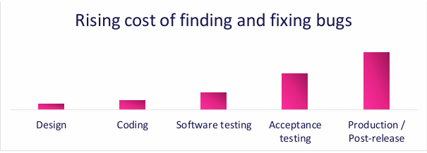
Figure 2: Rising cost of finding and fixing bugs – Illustrative
When developing software for our customers, Vintecc follows the V-model at the level of individual work packages. Different steps are taken when performing the whole process between talking with a customer to outline the next project phase and delivering that specific phase of the product, to minimise the time actually spent coding.
The objective of the V-model is inherently to deliver a working product. Following its left side of decomposing, the general requirements delivered by the customer through management tools, are broken into smaller pieces. These chunks are moulded into a new or an already existing architectural structure, with each small piece being fully written out functionally. After this, verification can already start on the left side of the V-model: are we building the product right? If the module designs correspond with the system requirements, both the coding phase and test development can commence (Figure 3).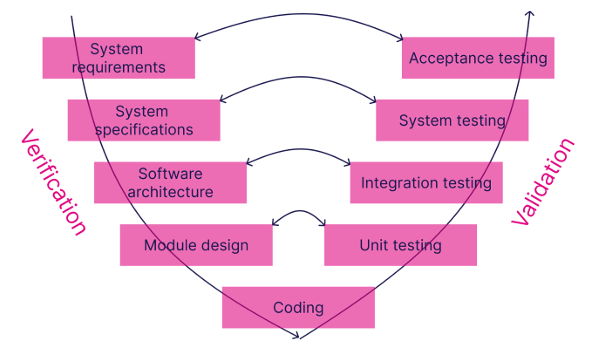
Figure 3: Representation of the V-model which Vintecc uses when developing.
These can occur simultaneously, after setting up the API structure of the models. One person can translate the module design into actual code, whereas another person can already start designing a test for that new (part of the) module, following our internal testing guidelines. As both the code and the unit testing are built from the same document (i.e. the module design document), it is best to have each developed by a different person, for independent understanding and verification of the module design translation.
Only testing the different small module cogs of the product is far from optimal. You wish to see the integration between different modules and see how they influence each other. You do not need the full system to test these functionalities, as they are limited to a relatively small subset of modules. When you wish to test the full system behaviour, virtual system tests mimic the behaviour of the actual machine and possible errors can already be retrieved before the software is incorporated into the physical product.
Through the process of the V-model, the system requirements of the customer are translated into the piece of the bigger puzzle that our software model in the physical product is. Our puzzle piece is tested on its strength in all directions, from the small modules to the full software stack (Figure 4).
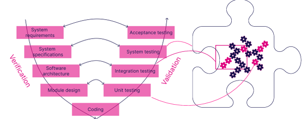
Figure 4: Visual representation of the V-Model applied to the software puzzle piece. A small cog represents a module, the pink box with the pink cogs inside represent an integration test to validate a certain functionality spread over different modules. Virtual system tests apply to the whole puzzle piece.
MATLAB environment
In our current chain of work, we use Simulink Test to validate software designed in Simulink and Stateflow, before generating production C/C++ code using Embedded Coder for deployment to the target system. All testing levels are tackled in a similar way using Simulink Test:
A test harness is built around the model under test (either a unit block for unit testing; multiple blocks for integration testing; the full model for system testing, either with or without a physics plant, for closed or open loop testing respectively).
A test sequence is implemented, where different approaches are performed, depending on the type of test phase:
a. Unit testing: Monte Carlo simulation for complex systems vs straightforward subset A_OUT of the output values is expected when subset A_IN is given as input value, to reflect the behaviour as designed on module level.
b. Integration testing: Focus is on behavioural testing of ‘upstream’ signals, i.e. signals that are generated in a model with an execution order after a model where that signal is used in, to reflect the software architectural choices made.
c. Virtual system tests: Verify the behaviour of the full system. Focus is on specific features and edge cases, with impact on different models. Each test is a well-defined situation to reflect the system specifications.
Closed loop system tests can often be constructed using a Simscape plant as a digital twin of the physical device to obtain even more realistic results.
Using the features of Simulink Test, custom criteria are added at the system test level to guarantee that certain unwanted behaviour (e.g. flickering of a certain signal; the order of operations/states/…; certain combinations of values/states/…) is not present in the full model.
When all these tests pass and the current work package is finished, a software release is generated with Embedded Coder for deployment on the physical system. In the meantime, it is perfectly possible that the physical system has already started its testing, based on the results of prior test runs, as features are implemented in parallel, giving the opportunity to already perform the isolated test runs on the physical unit. The testing suite can always be run at the end of the development of a feature using the CI/CD pipeline present in projects, through the actions taken in our Git repository.
Conclusion
Through Simulink Test, we are capable of maintaining and expanding our test suite in the same environment as our development takes place. This ensures a swift integration of all our different steps in the process and the ability to link every phase to its corresponding tests. This way, the software model already gains a good deal of confidence upon its release, before a deployment to its physical unit takes place. This is only one example where Vintecc applies Model-Based Design, as we encounter this challenge in projects involving embedded software for OEMs, autonomous robots in logistics, and complex mechatronic systems in sectors such as agriculture. As testing time on the actual machines is often scarce, starting acceptance testing as bug-free as possible is a significantly better starting point.


댓글
댓글을 남기려면 링크 를 클릭하여 MathWorks 계정에 로그인하거나 계정을 새로 만드십시오.