 Cleve’s Corner: Cleve Moler on Mathematics and Computing
 The MATLAB Blog
 Guy on Simulink
 MATLAB Community
 Artificial Intelligence
 Developer Zone
 Stuart’s MATLAB Videos
 Behind the Headlines
 File Exchange Pick of the Week
 Hans on IoT
 Student Lounge
 MATLAB ユーザーコミュニティー
 Startups, Accelerators, & Entrepreneurs
 Autonomous Systems
 Quantitative Finance
 MATLAB Graphics and App Building
Winners of eBAJA SAEINDIA 2019 use MATLAB and Simulink for their Vehicle Design
For today’s post, I would like to introduce you to Team Stallions from Nirma University. They recently secured overall 1st rank in eBAJA SAEINDIA 2019, Indore and are here to share their experience of using MATLAB and Simulink for their vehicle design.
—

From our previous years’ experience, we learned that simulation is an important part of the design process. This year, our aim was to build an efficient All-Terrain Vehicle (ATV) that can compete in eBAJA SAEINDIA 2019 competition where teams need to design an electric powered ATV. Hence, it was important to perform the simulations before we could finalize the design of our ATV. To demonstrate our approach, first let’s look at our challenges and requirements:
- Sizing and selection of components: Our major challenge was to select a proper motor and gearbox which could meet our design requirements.
- Estimation of State of Charge (SoC): The next requirement was to estimate the battery SoC so that we could select appropriate size of the battery for a drive cycle.
- Brake and steering calculation: Finally, we wanted to create a calculator to provide us the brake and steering performance calculations which could calculate the stopping time, Ackerman percentage, required turning radius, etc.
Having mentioned the challenges, now let’s have a look at how MATLAB and Simulink provided us a platform to provide a simulation-based solution to our problems.

Equation-Based Powertrain Model
We recorded the drive cycle of our vehicle using an inertial measurement unit (IMU) and used the Drive Cycle Source block from Powertrain Blockset to import the recorded drive cycle (Figure 1). This block gave us the liberty to import the data from different file formats.
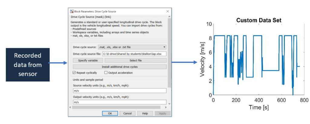
Figure 1: Drive cycle export
The recorded data and the other specifications of our vehicle were used to build a Simulink model (Figure 2). Our model is divided into four essential subsystems. Starting with the Force model subsystem, the drive cycle, weight of the vehicle including the driver, vehicle acceleration, and the tire radius are fed as input to the subsystem. Now, this model uses force equations to calculate the tractive force, torque, wheel speeds and the mechanical power. Further, these values are fed into the gearbox model subsystem which essentially increases the wheel speed and decreases the torque according to the gear ratio, considering the power losses. Now the motor inverter model takes these values and converts the mechanical entities into electrical entities and accordingly extracts electrical charge from the battery model. The model stops when the state of charge (SoC) of the battery pack reaches to a defined level.
Once our Simulink model was ready, we ran the simulations with different circuits and vehicle parameters. Hence, using this model we were able to perform multiple simulation trials to estimate the SoC and select the appropriate motors and gears.
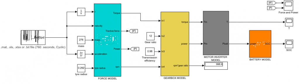
Figure 2: Simulink model
Steering and Brake Calculations
While designing an ATV, it is important that the driver is comfortable with the steering. Important. Initially, we used to use separate tools to perform the calculations and a separate tool for the visualization. Later, our seniors suggested us to use MATLAB App Designer, as it provides one platform to create user interface and run our mathematical calculations so that we don’t have to write glue code. We also realized that it would be great to build an app where we just need to input the values such as wheel base, track width, length of rack, etc. and visualize the results. Figure 3 shows the app built using MATLAB which gives us the following information:
- Tie rod design parameter
- Ackerman percentage
- Required turning radius
- Deviation of Ackerman geometry from the actual geometry

Figure 3: Steering calculation app
Similarly, we made an app for our brake calculations. The brake is a very crucial component for any vehicle it is necessary to calculate brake balancing and braking force of the vehicle. Also, it is necessary to design the brake parameter with actual conditions. Our previous calculations for “determination of brake disk diameter” and “determination of stopping distance” was very unrealistic as it gave 11 – 12 m as total stopping distance. Hence, we moved to energy conservation method to calculate the stopping distance. Figure 3 shows brake calculations we performed using MATLAB. Using the brake model, brake balancing is appropriately analyzed, and braking distance is simulated accordingly.
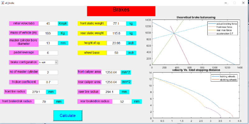
Figure 4: Brake calculation app
Conclusion
The simulation-based approach helped us to understand our design requirements. We are thankful for the video tutorials available on the MathWorks web page. These tutorials helped us to build our own models and apps. Going forward, we will explore more new features in MATLAB and Simulink which would help us to build a much more efficient car.


コメント
コメントを残すには、ここ をクリックして MathWorks アカウントにサインインするか新しい MathWorks アカウントを作成します。