Into the Mucube
Last time, when I was talking about permutohedra, we saw how truncated octahedra fill 3D space with no gaps. There are a number of shapes with this property, and they have the lovely old family name convex uniform honeycomb. There's another interesting family that is related to the honeycombs. They're called apeirohedra or "infinite skew polyhedra". You make the apeirohedra by removing some of the faces of a honeycomb. This gives you an infinite set of faces that divide 3D space into two halves. These two halves pass through each other in very interesting and complicated ways.
Today I'm going to take a look at the simplest of these. It's called the mucube. It's basically an infinite stack of cubes with half of the faces removed. I can draw a tiny piece of it like this:
x = [];
y = [];
z = [];
for i=1:5
    for j=1:5
        for k=1:5
            c = zeros(1,4);
            if mod(i+j,2)
                x(end+1,:) = [i i+1 i+1 i];
                y(end+1,:) = [j j j+1 j+1];
                z(end+1,:) = [k k k k];
            end
            if mod(j+k,2)
                x(end+1,:) = [i i i i];
                y(end+1,:) = [j j+1 j+1 j];
                z(end+1,:) = [k k k+1 k+1];
            end
            if mod(k+i,2)
                x(end+1,:) = [i i i+1 i+1];
                y(end+1,:) = [j j j j];
                z(end+1,:) = [k k+1 k+1 k];
            end
        end
    end
end
c = zeros(size(z'));
patch(x',y',z',c,'FaceColor',[.929 .694 .125])
view(3)
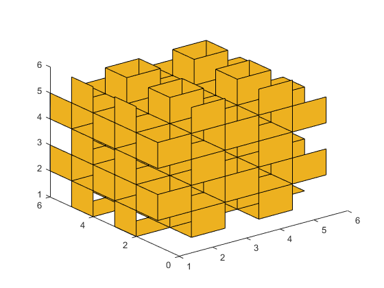
But it's very hard to figure out what we're seeing here, isn't it? Let's try again with a different colors for different faces.
cla
ax = gca;
cols = ax.ColorOrder;
colormap(ax,cols);
x = [];
y = [];
z = [];
fc = [];
for i=1:5
    for j=1:5
        for k=1:5
            c = zeros(1,4);
            if mod(i+j,2)
                x(end+1,:) = [i i+1 i+1 i];
                y(end+1,:) = [j j j+1 j+1];
                z(end+1,:) = [k k k k];
                fc(1,end+1,:) = cols(1+mod(k,2),:);
            end
            if mod(j+k,2)
                x(end+1,:) = [i i i i];
                y(end+1,:) = [j j+1 j+1 j];
                z(end+1,:) = [k k k+1 k+1];
                fc(1,end+1,:) = cols(3+mod(i,2),:);
            end
            if mod(k+i,2)
                x(end+1,:) = [i i i+1 i+1];
                y(end+1,:) = [j j j j];
                z(end+1,:) = [k k+1 k+1 k];
                fc(1,end+1,:) = cols(5+mod(j,2),:);
            end
        end
    end
end
patch(x',y',z',fc)
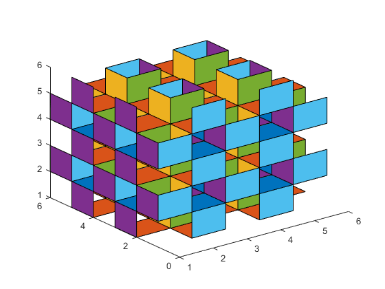
That helps a little, but not much. The problem is that we're trying to stand outside the mucube and look in. We really can't do that because the mucube is infinite. To really understand it, we're going to have to go inside.
Let's make a bigger one, and go in.
cla
x = [];
y = [];
z = [];
fc = [];
for i=1:25
    for j=1:25
        for k=1:25
            c = zeros(1,4);
            if mod(i+j,2)
                x(end+1,:) = [i i+1 i+1 i];
                y(end+1,:) = [j j j+1 j+1];
                z(end+1,:) = [k k k k];
                fc(1,end+1,:) = cols(1+mod(k,2),:);
            end
            if mod(j+k,2)
                x(end+1,:) = [i i i i];
                y(end+1,:) = [j j+1 j+1 j];
                z(end+1,:) = [k k k+1 k+1];
                fc(1,end+1,:) = cols(3+mod(i,2),:);
            end
            if mod(k+i,2)
                x(end+1,:) = [i i i+1 i+1];
                y(end+1,:) = [j j j j];
                z(end+1,:) = [k k+1 k+1 k];
                fc(1,end+1,:) = cols(5+mod(j,2),:);
            end
        end
    end
end
patch(x',y',z',fc)
axis off equal
view(3)
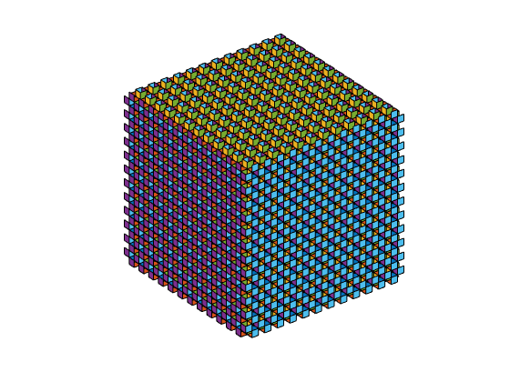
We need to do a few things to move the camera into the mucube.
We need to set the Projection to perspective.
I'm also going to set the CameraViewAngle because the default of 7 degrees would give us a very narrow view.
We'll also turn Clipping off and let the picture fill the entire figure.
Once I've done all that, I can move the CameraPosition into the mucube, and set the CameraTarget to be a short ways away in the direction we want to look.
ax.Projection = 'perspective';
ax.CameraViewAngle = 30;
ax.Clipping = 'off';

position = [14.5 14.5 14.5];
ax.CameraPosition = position;
ax.CameraTarget = position + [10 0 0];
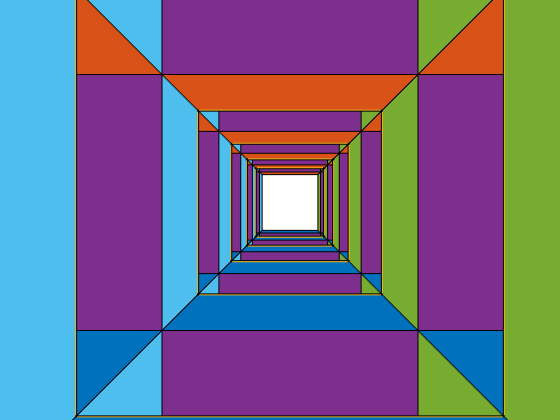
That's more like it!
What we see is that we're inside a space with infinite corridors going off in three orthogonal directions. In between these corridors are pillars which go in three orthogonal directions.
Inside those pillars, there's another infinite space of corridors. From the point of view of someone in that space, we're inside one of the pillars. These two infinite half-spaces are separated by the faces of the mucube, and it is not possible to pass from one to the other without going through a face.
Now let's try moving around our half-space.
We'll go in a circle around the pillar to our left.
nsteps = 150;
center = position - [2 0 0];
radius = 2.25;
for ang=linspace(0,2*pi,nsteps)
    ax.CameraPosition = center + radius*[cos(ang) sin(ang) 0];
    ax.CameraTarget = ax.CameraPosition + 10*[-sin(ang) cos(ang) 0];
    drawnow
end
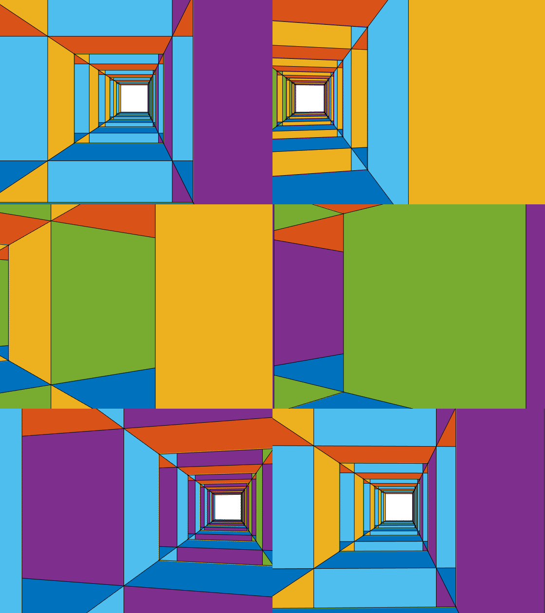
Because of the symmetry of the mucube, we could just as easily go in a circle around any other pillar. Let's try going around the pillar below us.
center = position - [0 2 0];
for ang=linspace(0,2*pi,nsteps)
    v1 = [0 cos(ang) sin(ang)];
    v2 = [0 -sin(ang) cos(ang)];
    ax.CameraPosition = center + radius*v1;
    ax.CameraTarget = ax.CameraPosition + 10*v2;
    drawnow
end
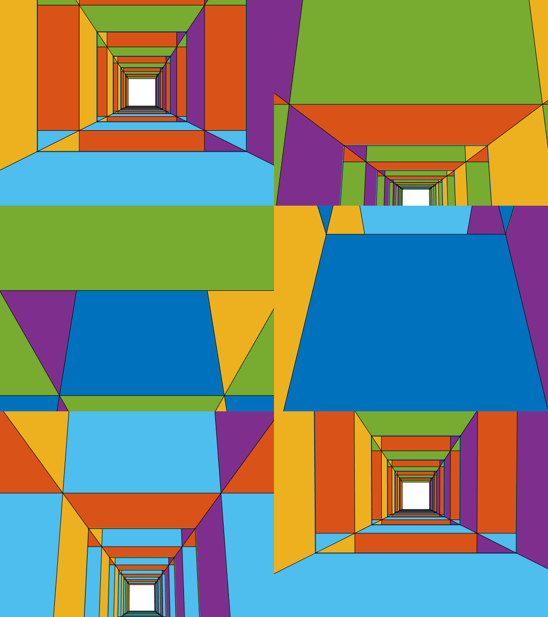
Wait a minute! That didn't look right, did it? Half way through things suddenly started going backwards. What happened?
It wasn't actually going backwards. What happened is that when we got half way around the circle, our camera suddenly flipped upside down. That's because of a property on the axes named CameraUpVector. The CameraUpVector is one of those properties that you don't need to think about very often. That's because, when the CameraUpVectorMode is 'auto', MATLAB Graphics will chose a value for the CameraUpVector automatically. It usually does a good job.
But this is a case where it doesn't do what we want. Once we're below the pillar and looking backwards, MATLAB Graphics decides that it'd be better to rotate the camera upside down. That might be a good choice for that CameraPosition and CameraTarget, but we know more. We know the entire path we're taking, and we don't want the camera to flip upside down in the middle.
We'll need to take control of our CameraUpVector.
for ang=linspace(0,2*pi,nsteps)
    v1 = [0 cos(ang) sin(ang)];
    v2 = [0 -sin(ang) cos(ang)];
    ax.CameraPosition = center + radius*v1;
    ax.CameraTarget = ax.CameraPosition + 10*v2;
    ax.CameraUpVector = v1;
    drawnow
end
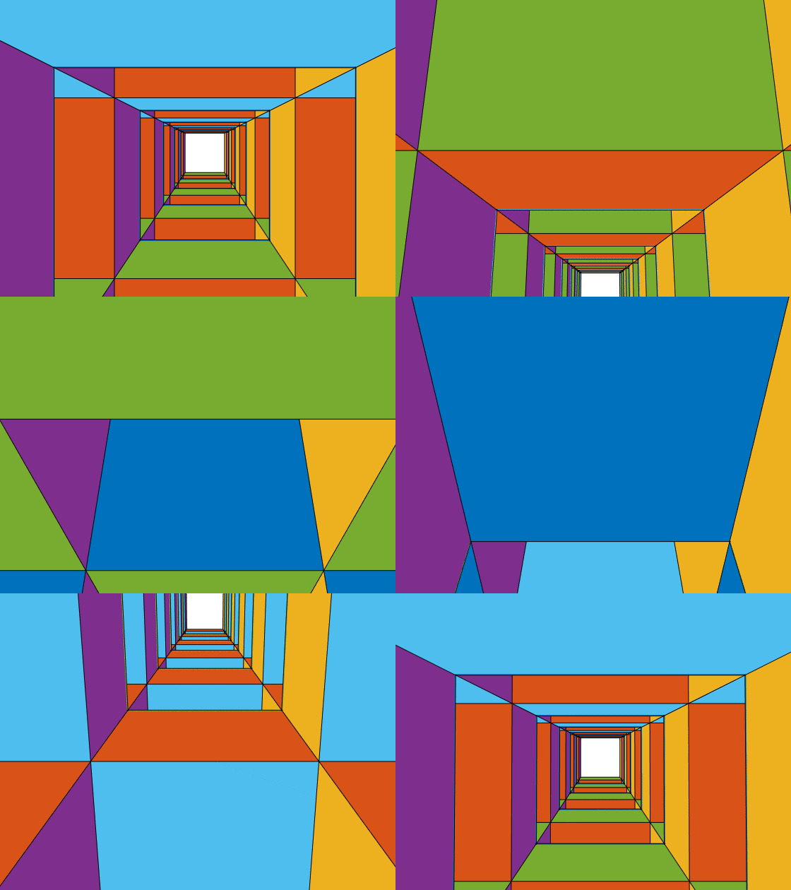
That looks better!
Can you make animations that fly around different paths through the mucube? For complex paths, computing the CameraUpVector gets a bit tricky. You might want to try some of the techniques I used in the posts about creating ribbons and tubes from parametric curves (link1, link2). What you're actually doing when you compute the CameraUpVector is establishing something called a Frenet frame on your curve.
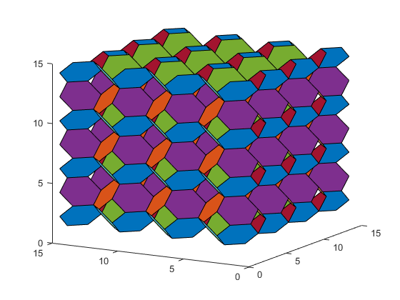
Can you do the same thing for the apeirohedron that corresponds to our infinite stack of truncated octahedra? That's known as the muoctahedron, and you make it by removing all of the quadrilateral faces from the stack of octahedra, leaving just the hexagons.
Here's some code to get you started:
n = 3;
np = factorial(3);
p1 = perms(1:3);
edges = [];
for i=1:np
    for j=(i+1):np
        diff = p1(j,:) - p1(i,:);
        if isscalar(find(diff==-1)) && isscalar(find(diff==1)) && (n-2)==length(find(diff==0))
            edges(end+1,:) = [i,j];
        end
    end
end
g = graph(edges(:,1),edges(:,2));
f = dfsearch(g,1)';

p1(:,4) = ones(np,1);
pts = p1 + repmat([-2 -2 -2 0],[np 1]);
xrefl = [-1 0 0 0; 0  1 0 0; 0 0  1 0; 0 0 0 0];
yrefl = [ 1 0 0 0; 0 -1 0 0; 0 0  1 0; 0 0 0 0];
zrefl = [ 1 0 0 0; 0  1 0 0; 0 0 -1 0; 0 0 0 0];

verts = [];
faces = [];
fcolors = [];
cols = lines(7);
for i=1:7
    for j=1:7
        for k=1:7
            mat = eye(4);
            cindex = 0;
            if mod(i,2)
                mat = mat*xrefl;
                cindex = cindex + 1;
            end
            if mod(j,2)
                mat = mat*yrefl;
                cindex = cindex + 2;
            end
            if mod(k,2)
                mat = mat*zrefl;
                cindex = cindex + 4;
            end
            ptmp = pts*mat + repmat([2*i 2*j 2*k 0],[np 1]);
            faces(end+1,:) = f+size(verts,1);
            verts = [verts; ptmp(:,1:3)];
            cindex = 1+mod(cindex,size(cols,1));
            fcolors(end+1,:) = cols(cindex,:);
        end
    end
end
clf
patch('Vertices',verts,'Faces',faces,'FaceVertexCData',fcolors,'FaceColor','flat')
view(-60,15)
- カテゴリ:
- Geometry


