
Building Janus: How a FIRST Robotics Team Engineered a Championship Robot
For this week’s blog post, we’re featuring FRC Team 2040 from the FIRST Robotics Competition as they reflect on their 2026 season and share how they used Simulink and WPILib to coordinate their robot Janus’s shooter and help the team return to the FIRST World Championship. If you are interested in using MATLAB and Simulink for your team, please visit our FIRST Robotics page or contact us at roboticsarena@mathworks.com. We’re excited to highlight their journey and hope you enjoy their insights!
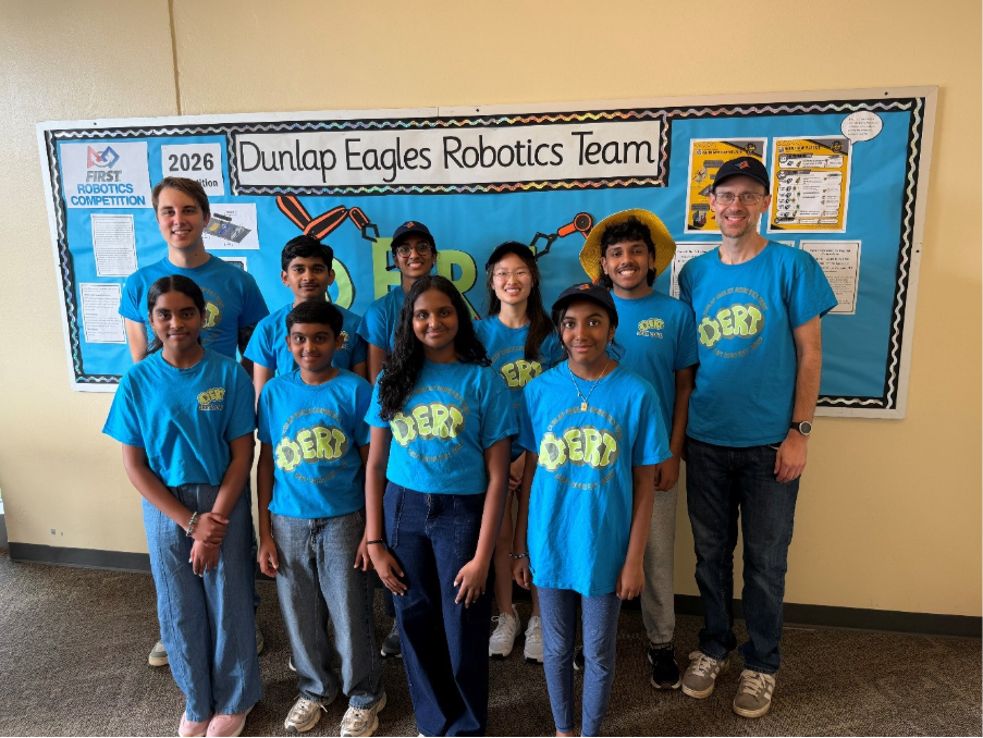
Meet FRC Team 2040
Hello everyone! My name is Anirudh Chalamkuri, and I am the programming lead and implement driver for DERT, FRC Team 2040, based in Dunlap, Illinois. I joined the team during my junior year, after watching them demo their 2024 robot at a school event.
Our team has competed in the FIRST Robotics Competition since 2007, and this year, after winning the Central Illinois Regional and being a finalist at the Greater Kansas City Regional, we qualified for and competed at the FIRST World Championship in Houston, Texas. This is a huge achievement and a very successful year for us, as we haven’t qualified for the World Championship since 2011.
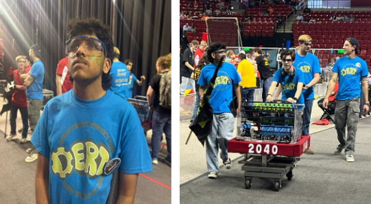
Our Robot: Janus
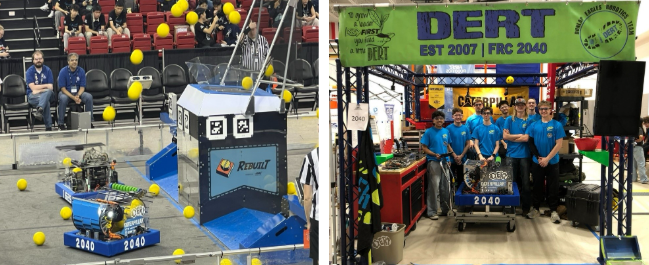
For the 2026 season, our team designedJanus,named after the two-faced Roman God of Beginnings.
The game this year Rebuilt, although much more complex, boilsdown tocompeting for and collectingas manypiecesof fuel (15cm in diameter high-density foam balls) froma sharedcenterzoneand scoring them into your alliance’s hub for points.
Our goal was to build a robot capable of scoring game pieces quickly and consistently from close to mid-range positions around the hub. Because of that, our robot falls under the ‘dumper-style’ category of bots, an archetype that generally relies less on shooting from long distances, and more on fast and repeatable cycles.
If you would like more detailed breakdown of our robot’s mechanical design, check out this flyer I designed detailing Janus’ mechanical specifications:
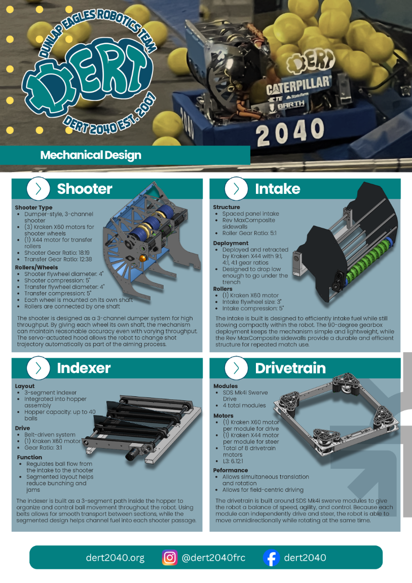
For the purposes of this blog, I’ll give a quick overview of our shooting mechanism. Our shooter is divided into three separate segments, allowing the robot to launch up to three fuel pieces at the same time. Each segment has its own path through the mechanism, including transfer wheels that move fuel into position and a set of shooting flywheels that launch it toward the hub.
The transfer wheels are powered by a single Kraken X44 motor and move fuel from the indexer into the barrel of the shooter. Once the fuel is in position, the shooting flywheels launch it out of the robot. Unlike the transfer system, the shooter is divided into three independent shafts, each powered by a Kraken X60 motor and equipped with flywheels. The robot rotates to aim horizontally toward the hub, while a hood driven by two linear actuators adjusts the angle of the shot.
Even a single shot relies on many parts of the robot working together at exactly the right time. A large portion of our programming work throughout the season went into refining that coordination so the robot could score as consistently and reliably as possible.
Our Design Approach
At the beginning of the season, our team had a new and very successful kickoff plan, coordinated by our team lead William Anderson. If you would like to read more about it and consider implementing it for your own FRC team, I have linked a PDF he created detailing the procedure and the reasoning below.
After deciding on the type of robot we would create, the programming team then set out to design the control systems for the scoring mechanism on our robot, we broke down our process like this:
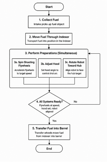
Although each mechanism has a specific role, the robot can score consistently only if all parts work together with great precision. This made the programming behind the shooter especially important and tricky. We needed to coordinate several motors, adjust the hood position, and control the robot’s direction while keeping the process as easy as possible for the drivers. This means most of this needed to be done automatically on the press of a button.
Why did we use Simulink?
Although our team had been using Simulink for three years prior, it paid off in a huge way this year.
Before joining the team, I had never used MATLAB or Simulink. I first learned how to use them during my junior year by watching Mr. Randy Anderson, our lead programming coach, teach us. During the following summer, the programming team gained more experience by working on several projects with a new programming mentor who joined our team. Those projects helped me learn the skills I needed before the start of the 2026 season.
Because I was already comfortable with hand-coding, Simulink did not feel that different to me. Once I understood how the blocks and signals worked, Simulink was just a more visual and intuitive way to write the same programming logic.
For newer programmers, however, Simulink was a game-changer. They did not need to memorize syntax before contributing to the robot. Instead, they could focus on the logic behind the program. Such as, what information the robot needed, what decisions it should make, and how each subsystem should respond. That made it easier for new members to get involved while still learning the core ideas behind programming. This was especially important because the majority of our programming team were rookies; in fact, my fellow programming co-lead, Melaina Humbles, and I were the only returning programming students for this season.
How We Integrated Simulink with WPILib
Integrating Simulink with WPILib, the open-source library used for FRC programming, was an exciting and technically challenging effort. The system was largely developed in 2023 by alumni/former team lead Janelyn Anderson, who also consistently returns to the team to update the codebase.
The basic idea is that once we create the control logic in Simulink, a build script uses Simulink Coder to generate C code from the model. That generated code is then integrated into our larger C++ and WPILib project.
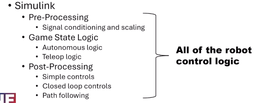
The handwritten C++ code handles the connection between Simulink and the physical robot. It passes sensor data and driver inputs into the model, runs the generated control logic, and then sends the resulting commands back out to the motors and other hardware.
This cycle runs every 20 milliseconds during the robot’s periodic loop:
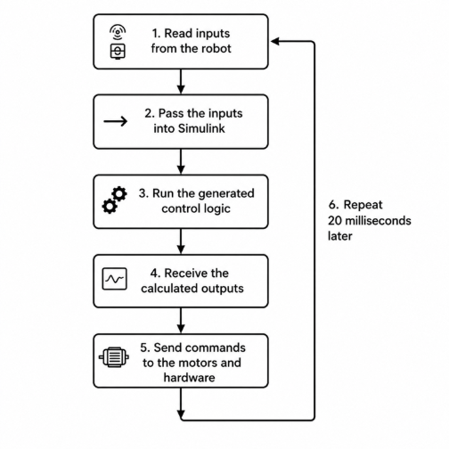
To make this easier to manage, our framework uses reusable C++ components. Each component handles a specific part of the robot and includes a pre-step function and a post-step function. The pre-step function collects information from the hardware and sends it into Simulink. The post-step function takes the output from Simulink and applies it to the robot. Setting up each of these components requires minimal programming and can be done quickly whenever required, so most of the attention and time can go towards the Simulink logic.
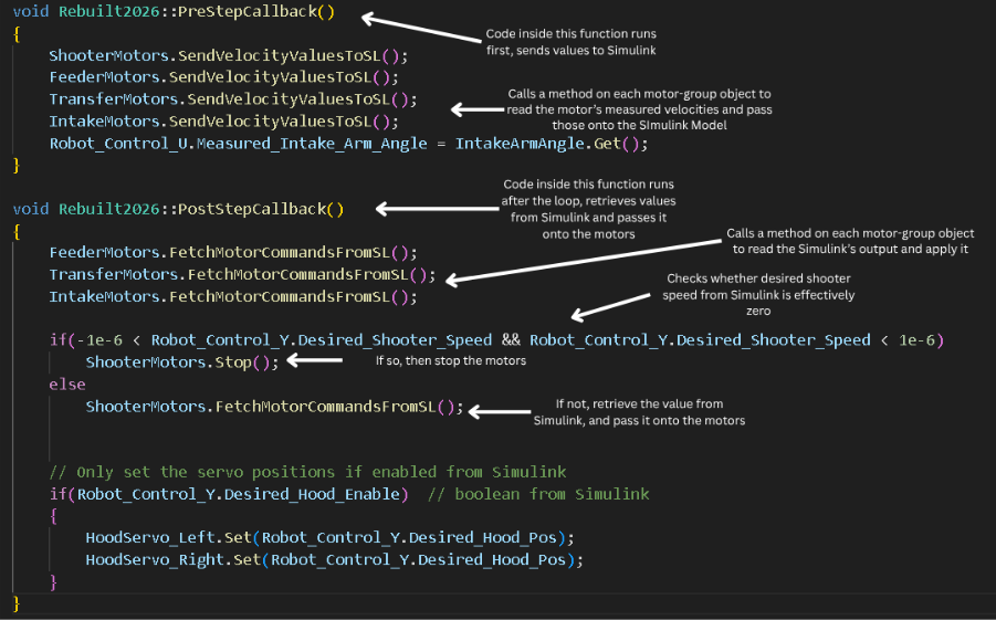
As you can see from the code snippet above, the amount of hand-code required is relatively minimal.
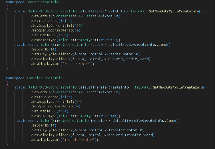
Janelyn also set up libraries that simplify the process of adding motors. Instead of rewriting a large amount of setup code each time a new motor is added, we can use wrappers to configure details such as the CAN ID, direction, and current limits in one place. Below is an example of two different categories of motors being created:
Another useful part of the framework is the ability to interact with certain values through Network Tables. These values can include PID constants, offsets, and other tunable parameters. We can adjust them through tools such as Glass or Advantage Scope while testing the robot, rather than rebuilding the entire program after every small change. The nature of this year’s game requires high precision, and being able to adjust parameters quickly on the fly during tuning saved a lot of time.
We can also use test points that display the values of important signals. This makes it easier to diagnose problems because we can see what the robot is measuring and what commands the model is producing in real time.
For example, while tuning the shooter, we could monitor values like:
- Target flywheel RPM
- Measured flywheel RPM
- Flywheel motor output
- Hood target position
- Measured hood position
- Whether the robot is aligned with the hub
- Whether the shooter is ready to release fuel
Now that I’ve gone over, at a high level, how the framework for Simulink integration works. Let’s delve into the Simulink code.
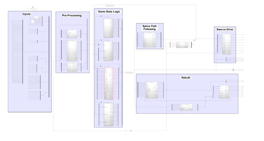
Above is a zoomed-out screenshot showing our primary Simulink Model for the robot’s controls. For today’s purposes, I will focus primarily on the “Rebuilt” section, more specifically the subsystem for shooting.
One of the main tools we used to control the shooter was PID control. A PID controller continuously compares a desired value, known as the setpoint, to the robot’s actual measured value. It then adjusts the motor output via various feedback loops(Proportional, Integral, and Derivative)to reduce the difference between the two. Instead of relying on a fixed motor output and assuming it will behave the same way every time, the controller constantly makes small corrections based on sensor feedback.
For our shooter, each of the three channels is powered by its own Kraken X60 motor. Before releasing fuel, the robot needs to bring each flywheel to its target speed. Rather than simply applying a fixed amount of power and assuming the wheels will spin at the correct rate, the program measures the actual RPM and adjusts the motor output as needed.
For example, if one flywheel is spinning below its target RPM, the controller increases its output. As the flywheel approaches the desired speed, the controller makes smaller corrections. This allows the shooter to respond to changes in the system, such as the brief drop in speed that can occur when fuel passes through the wheels.
Below is a Simulink Subsystem that adjusts the shooter motor PID gains and controls when the integral term is enabled.
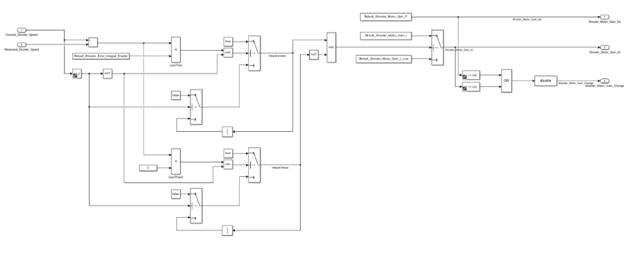
This subsystem adjusts the shooter motor PID gains based on how close the shooter is to its target speed. It subtracts the measured shooter speed from the desired shooter speed to calculate the current error, then uses several comparisons and logic blocks to determine whether the integral term should be enabled or temporarily disabled. There is also logic in order to remember the previous state and prevent the integral control from rapidly switching on and off between updates. The proportional gain is passed through directly, with no logic controlling it; meanwhile, the integral gain is selected based on the aforementioned logic. Finally, the subsystem checks whether the gain has changed and sends a signal telling the motor controller to update its PID settings.
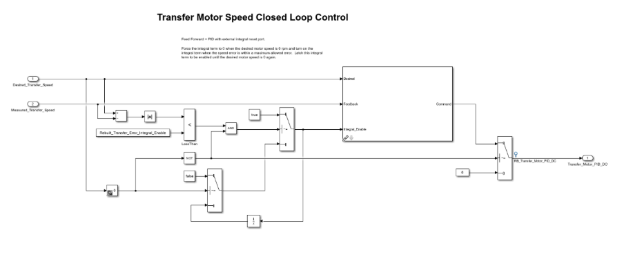
The previous subsystem adjusted the PID gains used by the shooter motors. Below is an example of how we used one of our custom PID library blocks to implement a complete PID control loop within a subsystem. The model compares the desired transfer motor speed with the measured speed and passes both values to the PID block with feedforward, which calculates the duty cycle required to achieve the target speed.
Shooting a fuel object requires several mechanisms to work together. The flywheels must reach the correct speed, the hood must move to the correct position, and the robot must rotate toward the hub before the transfer wheels release the fuel. All of these rely on processing vision input, doing calculations, and then transferring that accurately to motor commands.
The subsystem shown below combines several calculated outputs from other subsystems and uses logic gates to determine whether the robot is ready to shoot. It also decides whether the robot is prepared to unload or pass fuel, which are handled by separate functions.
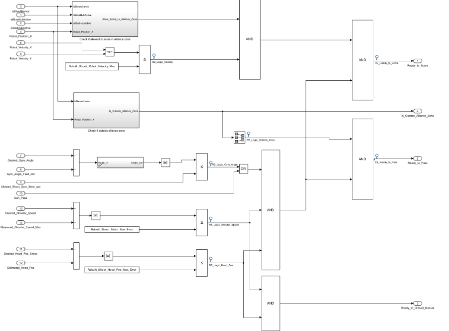
It verifies that the robot is in the correct field zone, moving slowly enough, aimed at the target, and that the shooter wheels and hood are at their desired settings. These conditions are combined so the robot only transfers and shoots the fuel once the required systems are ready.
After the robot evaluates its shooter speed, hood angle, alignment, and field position, those readiness signals are passed into this Stateflow chart. The chart controls when fuel is allowed to move through the final stages of the shooting system, preventing transfer and feeder wheels from activating before the robot is ready.
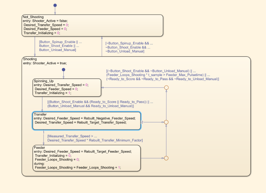
This Stateflow chart also organizes the shooting sequence into clear states. When the robot is not shooting, the transfer and feeder motors are stopped. Once a spin-up, shoot, or manual-unload command is received, the robot enters the shooting sequence and waits in the Spinning_Upstate while the shooter, hood, and alignment systems prepare. After the robot reports that it is ready to score, pass, or unload, it enters the Transfer state, where the transfer wheels move fuel from the indexer toward the barrel. Once the transfer wheels reach the required speed, the feeder activates to push the fuel through the shooter. The system returns to the spin-up state when the command is released, the shooting time limit is reached, or the robot is no longer ready.
With this Stateflow chart, PID loops, and many other subsystems that I unfortunately do not have the time to share, the robot is able to successfully score fuel into the hub!
A lot of work went into the code behind the robot throughout the season. It took plenty of testing, small adjustments, and troubleshooting to get everything working together the way we wanted. I was only able to highlight one of the main parts of our robot’s code here, so I will link our GitHub repository for anyone who is interested in looking through the full codebase and learning more about how the robot works!
Reflecting on Our 2026 Season
Making it to the FIRST Championship in Houston was a huge moment for our team. This is the best our team has ever done in its history. Making a deep playoff run at one regional is already an incredibly rare and exciting feat for us, but taking home the victory banner at one regional and then making it all the way to the finals at a second was something we never could have expected. After our unexpected win, our mentors and parent volunteers stepped up to raise the money and handle all of the logistics needed to get our team to Houston. We would not have been able to make the trip without their support.
At Houston, the robot performed well and helped us end our season with a 6-4 record in a competitive field filled with top-tier robots from across the world. It was so exciting to see Janus compete on that stage after months of designing, building, programming, testing, and fixing problems together as a team.
Although making it this far was something we were incredibly proud of, there are still areas we would have liked to continue working on and will likely work on throughout the offseason. With more time and a lot of adjustments to the code and vision system, we would have loved to implement accurate shooting-on-the-move on our robot. It would’ve helped combat some of the heavy defense that was played at Houston, and increase the amount of cycles our robotics able to perform each match.
Overall, making it to Houston was a fitting end to an incredible season. It gave us the chance to compete against some of the best teams in the world and see how far our robot had come since the beginning of the year. Although there were still areas we could have improved, the experience of reaching the Championship was something we will always be proud of, and we hope it marks the beginning of a new annual tradition for the team.
- カテゴリ:
- Robotics,
- Team achievements




コメント
コメントを残すには、ここ をクリックして MathWorks アカウントにサインインするか新しい MathWorks アカウントを作成します。