
Building a Virtual Robot: A BEST Robotics Team’s Journey with Simscape
Today, we’re talking to Carson Adams from Oak Ridge High School about how his team built a virtual model of their competition robot for the BEST Robotics competition. Over to you, Carson…
Hello! I am Carson Adams from Oak Ridge High School and a member of the Ridge Robotics team. I am here to talk about Cerebra, the latest robot made by Ridge Robotics. Competing in the BEST Robotics Competition, Ridge Robotics is a student-led team, based out of Oak Ridge High School with large ties to the Academy for Careers in Engineering and Science both based in Conroe, Texas. Our goal is to develop an inclusive environment where our members not only learn engineering skills but find a place they love. This message is what pulled me into the team.
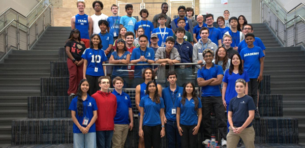
Ridge Robotics Team
My Story
As a Simulink and MATLAB user, I originally started through my sponsor who was interested in the Simulink Design award. With that small push, I jumped into the world of simulation and became very interested. With my almost 10 years of experience in Computer Science, it seemed that Simulink should be easy. However, this “easy” task ended up taking over 100 hours of hard work to learn the ins and outs of the program and constant iteration. In the end, I may not have been a natural, but I am proud to say that through effort I was able to win the national award last year. Of course, it wasn’t all trial and error, in fact, I had lots of help along the way from other resources and blogs. Some of the blogs I found useful were:
- Creating Virtual Robot Environments in Simscape: Assembling Robots and Importing from CAD – Using File blocks
- Creating Virtual Robot Environments in Simscape: Adding Physics, Object Interactions, and Autonomy – To more fully understand collisions
- And especially these onramps:
- MATLAB – To learn MATLAB
- Simulink – To learn the basic controls of Simulink
- Simscape – To learn how modelling works
- Multibody Simulation – To learn how modelling pieces works
The Goal
In the BEST Robotics competition, MathWorks sponsors the Simulink Design Award, which encourages teams to use MathWorks products, primarily Simulink, to simulate or program their robots. Teams can demonstrate their use of MathWorks tools through robot programming with libraries and Simulink, or through robot modeling using Simscape and Simscape Multibody. For my submission, I focused on the robot modeling aspect, so this blog will primarily explore the details of that approach.
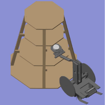
The Claw in Use
The Approach
We started modelling the robot after it was built. By doing so, it is possible to take apart the robot systematically enabling near perfect reconstruction. For this project, I separated the robot into the portions that the robot was built in. For example, the arm system was built in Simscape separate from the wheels. To construct the systems in Simscape, I look at the robot and note how the individual pieces fit together and what pieces move. Additionally, I am very lucky that I have a teammate, Nicolas Oliveira, who creates some excellent CAD. I used his individual CAD files using file blocks to put together the actual pieces of the robot. They were then moved using rigid transforms.
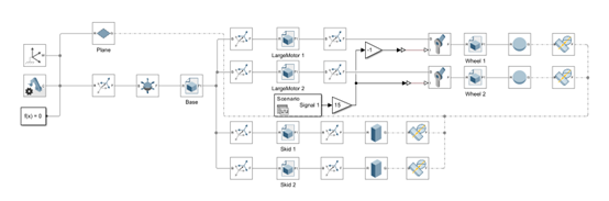
Simscape model of the Claw Subsystem
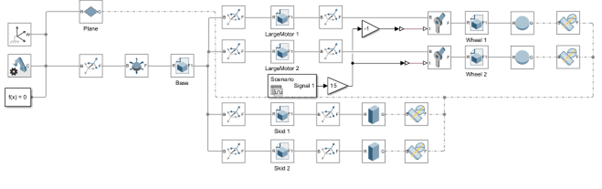
Simulink model of the Movement Subsystem
Often when working with Simscape, I find difficultly with collisions between objects because of the complexity of the objects. For instance, the wheels collide with the ground but the complexity of the wheel file blocks makes the simulation run very slowly. In this case, I perfectly covered the wheels in the basic sphere block which has less computationally intensive collisions. Generally, with collisions it is useful to create shadow objects, called proxies, that serve as a collision boundary or hitbox for the actual object. The simpler, the better.
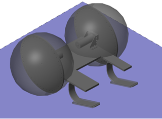
Visual of Wheel Proxies
Another tricky part of simulating in Simscape Multibody is when a part needs to rotate around one axis that is not the Z-axis. A revolute joint is a simple joint that allows for rotation around 1 axis only. The catch is that the revolute joint only allows for the Z-axis to be the axis of rotation. Well, if the Z-axis is locked, an equivalent option to changing the axis, is to change where the Z-axis is. The rigid transform block allows hardcoded rotation around the other axis. So, in order to rotate along a particular axis, rotate 90 degrees along the other. After the pivot, apply the inverse rotation of -90 or 270 degrees.
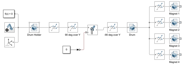
Correcting the Pivot Axis
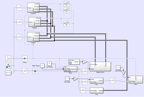
Visual of Collision Wiring
The model can be found at this link: Model Github Repository
Lessons Learned
Throughout it all, a few things stuck with me namely the value of hard work and community. Without putting in the effort, it is very hard to gain the skills needed to learn. And without the places to learn, it is hard to get started. With these two values, our team has grown and will continue a tradition of using Simulink.
- カテゴリ:
- Robotics


コメント
コメントを残すには、ここ をクリックして MathWorks アカウントにサインインするか新しい MathWorks アカウントを作成します。