
Developing CT Reconstruction Workflows in MATLAB: From FDK to AI-Based Methods
This post is authored by Sagar Hukkire, Senior Application Engineer at MathWorks, and Visa Suomi, Medical Devices Industry Manager.
Computed tomography (CT) reconstruction transforms raw X-ray projection data into clinically useful cross-sectional and volumetric images. Cone-beam CT (CBCT) is particularly demanding: its wide cone angle and large detector coverage increase sensitivity to scatter, truncation, geometric calibration, and view-sampling effects.
At the same time, engineering teams must balance image quality, acquisition time, radiation dose, and computational cost. A scalable CT reconstruction workflow must therefore support rapid experimentation, hardware acceleration, AI-based enhancement, and a practical path to deployment. This need is growing as detector sizes increase and low-dose and sparse-view acquisitions become more common.
Reconstruction Approaches
- Filtered back projection (FBP) with Feldkamp-Davis-Kress (FDK) reconstruction - a fast analytical baseline for circular CBCT acquisitions.
- Hybrid Iterative Reconstruction (HIR) – a physics-based refinement approach that improves data consistency and helps suppress artifacts.
- Deep Learning with a U-Net – a learned enhancement stage that maps baseline FDK slices toward higher-quality target reconstructions.
This blog presents an end-to-end CT reconstruction pipeline implemented in MATLAB® that combines three complementary approaches. The unified workflow supports GPU acceleration, visualization, validation, CUDA® code generation, and regulated medical-device software development aligned with IEC 62304.
Workflow Overview
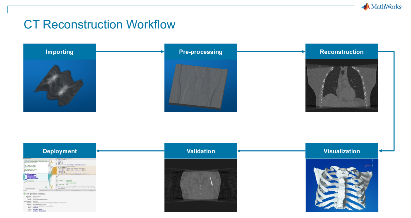
The workflow spans data import, preprocessing, reconstruction, visualization, validation, and deployment. It follows the same progression as the related MRI reconstruction series: begin with a reliable analytical baseline, add physics-based refinement, and introduce AI where it provides measurable value.
Why Combine Multiple Reconstruction Approaches?
CT reconstruction requires trade-offs among acquisition speed, radiation dose, image noise, spatial resolution, and artifact suppression. Dense, high-quality scans can improve reconstruction fidelity but may increase dose or acquisition time. Faster or lower-dose scans are attractive in practice, yet their noisier or less complete projection data can make reconstruction more difficult.
Rather than relying on a single “silver bullet” algorithm, this workflow brings several reconstruction strategies into one environment. Engineers can compare methods, understand the trade-offs, and build a practical path from algorithm exploration to deployment.
- Establish a reliable baseline: FDK reconstructs a full 3-D volume quickly and provides an interpretable reference point.
- Improve difficult scans: HIR keeps the acquisition model in the loop and refines the volume using projection-domain residuals.
- Use AI as an enhancement layer: the U-Net learns to reduce residual artifacts and improve slice appearance after physics-based reconstruction.
By unifying these approaches in MATLAB, engineers can prototype quickly, inspect intermediate results, validate image quality, and prepare selected algorithms for GPU execution and CUDA code generation without maintaining disconnected toolchains.
1. Baseline Reconstruction with FDK
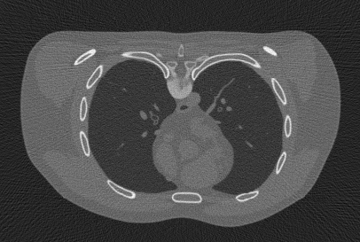
We begin with Feldkamp–Davis–Kress (FDK) reconstruction, an analytical baseline for circular CBCT acquisitions. FDK is fast, deterministic, and directly linked to the acquisition geometry. It reconstructs a 3-D volume by applying projection weighting, filtering, and back projection to the measured projection stack.
Dataset and Simulation Setup
For this example, we used the XCIST simulator to generate CBCT projection data. The raw projection dataset is available through MathWorks support files.
% Load projection data and run FDK reconstruction
projectionData = fullfile(dataDir, "CBCT_lowDose_Projections.mat");
volFDK = reconFDK(projectionData, 'Verbose', true);

% Inside reconFDK.m
S = load(inputMat);
P = S.P;
angles_rad = S.angles_rad(:)';
FDKvol = simpleFDK_CBCT_vox(P, angles_rad, DSD, DSO, ...
    [du dv], [dx dy dz], nx, ny, nz, 'ramp', ...
    'u0', u0, 'v0', v0, varargin{:});
How it works. FDK applies geometry-aware weighting and ramp filtering to each projection before back projecting the filtered stack into a 3-D volume. The result is available immediately for review, quality checks, or use as the input to HIR and deep-learning stages.
2. Refinement with Hybrid Iterative Reconstruction
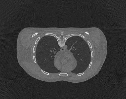
Hybrid Iterative Reconstruction (HIR) improves the initial FDK volume by repeatedly comparing simulated projections from the current estimate with the measured projections.
The resulting residual is back projected to update the volume, while regularization stabilizes the reconstruction and suppresses noise.
% Start from the FDK result and refine iteratively
volHIR = reconIR(projectionData, volFDK, 'Verbose', true);

% Core HIR update in reconIR.m
Ax = forwardProject_CBCT(x, angles_rad, DSD, DSO, ...
    [du dv], voxel_size, nu, nv, u0, v0, ...
    'UseGPU', UseGPU, 'NumSamples', numSamples);
res = single(P) - single(Ax);
grad = simpleFDK_CBCT_vox(res, angles_rad, DSD, DSO, ...
    [du dv], voxel_size, nx, ny, nz, 'ramp', ...
    'u0', u0, 'v0', v0, 'UseGPU', UseGPU);
reg = lambda * (x - imgaussfilt3(x, sigG));
x = x + alpha * (grad - reg);
How it works. Each iteration performs four steps: forward projection, residual computation, back projection, and regularization. Keeping measured projection data in the loop is especially valuable for low-dose or sparse-view scans, where analytical reconstruction alone may leave streaks, noise, or structural inconsistencies.
3. Deep-Learning Enhancement with U-Net
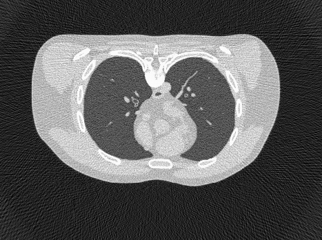
The third approach uses deep learning to enhance CT slices reconstructed with FDK or HIR. Rather than replacing the physics-based workflow, a U-Net serves as a learned image-to-image enhancement stage. In this example, the network maps FDK-quality slices toward higher-quality targets, such as HIR outputs.
% Train a U-Net that maps FDK slices toward HIR-quality slices
[volDL, net, info] = reconDL(volFDK, volHIR, 'Verbose', true);

% Key training steps in reconDL.m
lgraph = buildUNet(inputSize, BASE_CHANNELS, ENCODER_DEPTH);
options = trainingOptions('adam', ...
    'InitialLearnRate', 3e-4, ...
    'MiniBatchSize', 8, ...
    'MaxEpochs', 60, ...
    'ExecutionEnvironment', char(opt.ExecEnv));
net = trainNetwork(dsTrainPrep, lgraph, options);
yPredVol(:,:,k) = tiledPredict2D(net, sliceN, tile, overlap);
How it works. The workflow prepares paired reconstructed slices, normalizes the data, creates training and validation partitions, trains a 2-D U-Net, and applies tiled prediction to larger slices. Used as an enhancement layer, the network can focus on residual artifacts and subtle quality improvements instead of learning the complete CT reconstruction problem from scratch.
Verification, Validation, and Deployment
Reconstruction algorithms are only one part of a practical CT workflow. Engineering teams also need visualization, verification, validation, performance benchmarking, and a route to deployment. Because all three reconstruction stages are implemented in MATLAB, the same environment can support both exploratory development and production-oriented engineering.
For a 600 × 600 × 360 projection example running on an NVIDIA® Tesla T4 GPU, acceleration substantially reduced reconstruction time:
| Reconstruction Method | Before Optimization (s) | After Optimization (s) | Time reduction (%) |
|---|---|---|---|
| FDK-based CUDA Reconstruction | ~400 | ~7 | ~98.3% |
| Hybrid Iterative Reconstruction | 731 (per iteration) | ~27 | ~96.3% |
These results demonstrate that GPU acceleration and code generation are core parts of the workflow, not optional add-ons. The broader engineering workflow includes:
- Automatic testing and verification: modular functions make it easier to add smoke tests, regression checks, and quantitative comparisons across reconstruction stages.
- Interactive visualization and validation: reconstructed volumes can be inspected with Medical Imaging Toolbox™ using slice-based and volume-based views.
- Parallel, GPU-aware execution: Accelerated MEX functions and CUDA-capable hardware make realistic 3-D reconstruction experiments more practical.
CUDA code generation and deployment. MATLAB Coder™ and GPU Coder™ can generate accelerated MEX functions or deployment-oriented CUDA code from selected reconstruction entry points, with support for IEC 62304-oriented development workflows.
% Generate a CUDA MEX for the FDK entry point
cfg = coder.gpuConfig('mex');
cfg.GenerateReport = true;
inputs = {P, angles_rad, DSD, DSO, du, dv, u0, v0, ...
    dx, dy, dz, padFactor};
codegen -config cfg -args inputs reconFDK_codegen
GPU acceleration and code generation allow CT reconstruction methods developed in MATLAB to scale from desktop prototypes to specialized hardware. This helps bridge algorithm research, AI experimentation, and integration into production-oriented medical imaging systems.
Conclusion and Key Takeaways
Combining analytical, iterative, and AI-based reconstruction in one MATLAB workflow addresses the varied requirements of modern CT systems. A unified environment streamlines raw-data import, reconstruction, testing, visualization, validation, GPU acceleration, and code generation.
The main takeaways are:
- FDK reconstruction provides a fast and interpretable baseline for CBCT data.
- Hybrid iterative reconstruction improves fidelity by combining forward projection, residual correction, back projection, and regularization.
- Deep learning can enhance reconstruction quality when trained and validated with representative target data.
- GPU acceleration and CUDA code generation help bridge the gap between research prototypes and deployable reconstruction pipelines, with the example workflow showing about 57× speedup for FDK and about 27× speedup per iteration for HIR on an NVIDIA® Tesla T4 GPU.
Together, FDK, HIR, and U-Net enhancement create a flexible workflow in which classical reconstruction and AI reinforce each other. Engineers can iterate quickly, compare trade-offs clearly, and tailor CT reconstruction pipelines for both image quality and deployment readiness.
Try the Examples
- Category:
- Deep Learning


Comments
To leave a comment, please click here to sign in to your MathWorks Account or create a new one.