Transparency in 3D
Transparency in 3D
Transparency is a very useful feature when creating pictures in 3D. But there are a suprising number of things to think about when you're using transparency in 3D.
Let's look at a simple example to explore some of these issues.
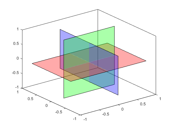
First we'll create a patch with three rectangular faces.
u = [-1; 1; 1; -1];
v = [-.67; -.67; .67; .67];
w = [0; 0; 0; 0];
h = patch([u,v,w],[v,w,u],[w,u,v],zeros(4,3), ...
          'FaceVertexCData',eye(3),'FaceColor','flat');
view(3)
box on

Next we'll make them partially transparent.
h.FaceAlpha = 1/3;

Notice that there are two areas where we see just the blue and green patches.
a1 = annotation('textarrow','X',[.725 .6125],'Y',[.05 .375],'String','Green in back of Blue');
a2 = annotation('textarrow','X',[.365 .47],'Y',[.93 .67],'String','Green in front of Blue');

But if we look closely, they're not the same color. The upper left area is greener, and the lower right area is bluer.
a1.String = 'Red=0.44, Green=0.67, Blue=0.78';
a2.String = 'Red=0.44, Green=0.78, Blue=0.67';

Why is that, and where do those numbers come from?
When we draw a transparent object, the color is determined by compositing the object using a blend function that looks like this:
$$C_{after} = \alpha*C_{object} + (1-\alpha)*C_{before}$$
When we draw overlapping transparent objects, the result is the product of multiple compositing operations. The blending functions of the compositing operations multiply like this:
$$C_{after} = \alpha_2*C_{object2} + (1-\alpha_2)*(\alpha_1*C_{object1} + (1-\alpha_1)*C_{before})$$
If you stick our colors and alphas into those equations, you'll get the numbers we saw earlier.
a1.String = '\alpha Blue + (1-\alpha)(\alpha Green + (1-\alpha)White)';
a2.String = '\alpha Green + (1-\alpha)(\alpha Blue + (1-\alpha)White)';

The reason we have different colors in these two cases is that the blending function doesn't commute.
$$A \otimes B \neq B \otimes A$$
There's another important point you should notice here. When we're drawing opaque objects (i.e. alpha=1), then the only thing that affects the final color of the pixel is the color of the last object to be drawn. But when we're drawing transparent objects (i.e. alpha<1), then the final color of the pixel is affected by the colors of all of the objects that touch that pixel, and the order matters because the blending function doesn't commute. In the upper left, we needed to draw the blue patch before the green. But in the lower right, we needed to draw the green patch before the blue.
This means that depth sorting transparent objects is inherently more complex than depth sorting opaque objects. For the same reasons that MATLAB's max function is simpler and faster than its sort function, the opaque depth sort is simpler and faster than the one we use for transparent objects.
The depth sort for opaque objects is a simple one called Z-buffering. For depth sorting the transparent objects, there are a number of different choices. Each of them has its own strengths and weaknesses. In MATLAB Graphics, we do this depth sort with a technique called Order Independent Transparency, or OIT for short. We chose OIT because it works well on the current generation of graphics hardware, although there are still a few graphics cards which don't support it.
OIT's biggest weakness is that it struggles when it encounters objects with exactly the same depth. We can actually see that in this picture. Those faint lines where the patches intersect are caused by that.
The other thing you may have noticed is that when OIT kicks in, the antialiasing is lost. That's because OIT is implemented using the same resources as GraphicsSmoothing and we can't currently do both at the same time.
In earlier versions of MATLAB we didn't use the graphics hardware to sort transparent objects. This meant that it didn't handle intersecting objects very well. Here's what R2014a did with this picture:

You can actually get a very similar effect with the new graphics system by setting the SortMethod, although that will affect the opaque objects as well as the transparent ones. When SortMethod is set to childorder, then all of this gets a lot simpler. That's why you usually don't have to worry about these issues when you're drawing 2D scenes.
Now that we have a 3D scene with transparency, we might want to print it. There are a few more things to think about when we print 3D transparency.
By default, when you print we use a sorting technique which is more like the one that MATLAB used on screen before R2014b. This means that it isn't going to handle this intersecting patch case well.
print -dpdf transparency.pdf

Even worse, if you're printing to one of the PostScript file formats (.PS and .EPS), then you need to be aware of the fact that they do not support transparency at all! That's because colors in the PostScript language are all opaque and do not have alpha values.
print -dpsc transparency.ps

That means that if you're using transparency, you'll either need to output to a file format which does support alpha (such as .PDF) or do the compositing before writing the results to the file.
The easiest way to do the compositing before writing the results to the file is to tell the print command to use OpenGL. When you do that, MATLAB will use OIT to generate an image with the correct sorting and compositing, and then save that image in the .PS file. But when you do this you might want to increase the resolution because the default is to use the screen resolution.
print -dpsc -opengl -r600 transparency_opengl.ps

I hope that gave you some insight into what's happening when you use transparency in 3D with MATLAB Graphics.
- Category:
- Rendering


