 Cleve’s Corner: Cleve Moler on Mathematics and Computing
 The MATLAB Blog
 Guy on Simulink
 MATLAB Community
 Artificial Intelligence
 Developer Zone
 Stuart’s MATLAB Videos
 Behind the Headlines
 File Exchange Pick of the Week
 Hans on IoT
 Student Lounge
 MATLAB ユーザーコミュニティー
 Startups, Accelerators, & Entrepreneurs
 Autonomous Systems
 Quantitative Finance
 MATLAB Graphics and App Building
Hydraulic decoupled suspension – how to get things running smoothly
In the first part of this post, I introduced the hydraulic decoupled suspension concept designed by Timothy Novotny and Alex Hönger from AMZ Racing.
In this second part learn about their design process and how they verified and tested the hydraulic decoupled suspension.
Dimensioning
A question about the weight target was asked during their presentation. Alex’s answer was to be expected: “Our goal was to have a lighter system than the previous!”. Admittedly, it is a bit tricky to do a net comparison of weight because the new system is very different. By assessing conservatively, they ended up with 1kg heavier than last year’s concept where most of the added weight comes from shielding the hydraulic pipes. These had to be made from PTFE with braided steel shielding to comply with the rules.

The hydraulic decoupled suspension is a nice opportunity to accumulate heavy items such as the central unit low and close to the center of gravity (COG). The team decided on locating the central unit just behind the driver where it is easy to access and helps to keep the package tight.
While researching for hydraulic components, especially cylinders, Timothy and Alex recognized that it is impossible to get exactly what they needed, mainly because hydraulic components are typically not optimized for lightweight design. Thus, they were forced into designing their own hydraulic cylinders.
The team already accepted some risk when deciding for the concept, but now the risk increased. What if they could not manufacture the system? Or even more fundamentally, what if their design would not fulfill its tasks? Alex was asked whether they were considering a back-up system. His answer was “Yes, but we didn’t build one”. At this point in the process, the AMZ Racing team made a bold decision and trusted their suspension gurus who were convinced that they could get it done.
Manufacturing and Assembly
At the end, Alex and Timothy designed about 60 custom parts and manufactured them with the help of partners. The major and most complex assemblies are certainly the three cylinder units.

As depicted in the main concept (see part 1 with animated GIF), many parallel cylinders needed to be integrated. For example, the pitch cylinder consists of 4 chambers, all packed tightly together. The heave cylinder consists of 8 chambers – 4 of them open to the atmosphere. By arranging in one line, the force flow could be improved a lot. During construction, it was all about shortening the axial length while maintaining enough stroke for the cylinders. Alex puts it this way: “By choosing an extreme motion ratio you can shorten the cylinder length quite significantly by just decreasing the stroke. But this increases the forces, […]. So, it’s a trade between stroke and forces. It was literally a fight for every tenth of a millimeter of axial length.” Furthermore, a major concern was whether they would be able to bleed the system and get all the air out. Hence, in the design stage, every chamber got a bleed access at the highest position over ground.

At one point, the entire project was at stake. During assembly and early sub-component tests, AMZ found that sealing a complex 120bar system is challenging and that the surface finish of cylinders is a key criterion to achieve that. Alex and Timo faced severe problems with the finish of the inner sealing surfaces made of Ni-coated aluminum (see photo). Main parts had blisters and even the replacement ones were not safe to use. This would lead to breaking seals in a short time. By literally getting their hands dirty and improving the surface finish manually, they got the problems under control. In my mind, this is a perfect example of difficulties that I mentioned in the introduction. These appear in the best-planned projects and are impossible to foresee. AMZ resolved them with dedication and massive manual effort. And to be very honest, there was no other option because accepting failure would mean: ending the car project and making efforts of the entire team AMZ obsolete, at least for the 2018 season. Which, I guess, was never an option.

Find here an illustration of the entire system mounted in the 2017 season racecar called pilatus
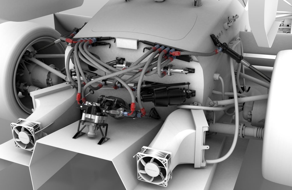
I hope you agree that looking at this illustration pursuing to understand the way the hydraulic system works is causing a big headache. Alex admitted that while designing “most of the resources were spent on the cylinders and attaching them. Little time was spent in the connection of the cylinders.”. But one way or the other, all cylinders must be connected to the dampers near the wheels. This means having hydraulic lines through the already tightly packaged chassis. Alex’s ideal world would also include a pressure sensor as well as an oil adjustment cylinder. Again, many hours and probably a few confrontational discussions later, AMZ came up with an approach of minimized parts size while keeping them easy to manufacture.
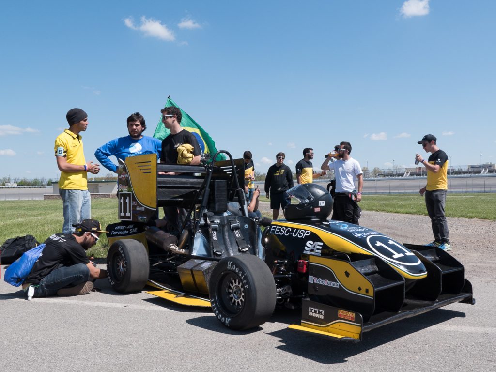
Racetrack Testing
Let’s have a look at the system in action. Enjoy this video as it will show most of the moving parts as well as vehicle parameters helping us to understand what is actually happening. The run was made during a postseason test on a rather bumpy and curvy track. Alex noted that the car was driven by an unexperienced driver – Him.
Admittedly, I replayed the video many times and enjoyed observing the gauges for speed, torque, steering-angle, as well as the g-g plot and position on track while trying to imagine the suspension modes. Great job Alex in combining the essence in one video and sharing it with us!
To illustrate the benefits on the track, Alex also provided data. The two graphs below compare gotthard (2016’s car) and pilatus (current). They show the load difference between the two wheel-pairs on the diagonal versus the lateral acceleration of the car.
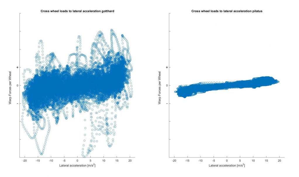
For perfectly unsprung warp, these cross-wheel loads would cancel each other out. However, setting a certain roll balance connects roll and warp which results in nonzero cross-wheel loads: the higher the lateral acceleration, the higher the deviation should be.
The thin band of data points in the pilatus graph nicely illustrates that setting the roll balance works like a charm. This is finally confirmation that the concept of hydraulic fully-decoupled suspension can be used in racecars. The range of y-values results from friction of the hydraulic components and particularly the tires. In comparison, gotthard’s plot reveals that warp is not unsprung. The y-range of data points is much higher resulting from, e.g., bumps in the track. This transfers many more unnecessary loads to the chassis.
Apart from the proof of concept that brings a smile to the engineer’s face, let’s not forget about a much more important factor. The car’s behavior is much more balanced helping the driver to perform at the limit and drive faster.
Conclusion
I think, Timothy and Alex grew to engineering adults during the project. They were given the opportunity to execute a brilliant idea and they coped with the challenges that nobody could imagine at first sight. To me, they are role models for students entering student competitions.
AMZ Racing and I are looking forward to your questions and a lively discussion in the comments section of this article!
All images on that page © AMZ.


评论
要发表评论,请点击 此处 登录到您的 MathWorks 帐户或创建一个新帐户。