Hydraulic decoupled suspension – the journey starts with a bold idea
Great ideas don’t always stand the test of time. It may be due to some drawbacks that knock out the great advantage, or it simply is too expensive or difficult to implement. The following article will share a contradicting example. Enjoy this engineering success story of originality and rock-solid engineering skills.
Timothy Novotny and Alex Hönger, from AMZ Racing of ETH Zurich, presented their concept of a hydraulic decoupled suspension at the Formula Student Germany Workshop in October 2017 [video link]. AMZ Racing is one of the teams where model-based design is part of their DNA for racecar development. They use MathWorks products for a multitude of applications such as lap-time simulation, control design, optimize trajectory planning for their driverless car and many more.
For that specific project, the team accepted significant risk by allowing Timothy and Alex to pursue their bold idea from early stage concept until functioning in a winning racecar. The result is a proof what bright minds in conjunction with a powerful team and its partners can achieve.
Some Basics
The primary goals of a racecar suspension can be summed up briefly. It should maximize overall grip while minimizing wheel load variations. Furthermore, it should reliably exhibit predictable and driver-friendly behavior.
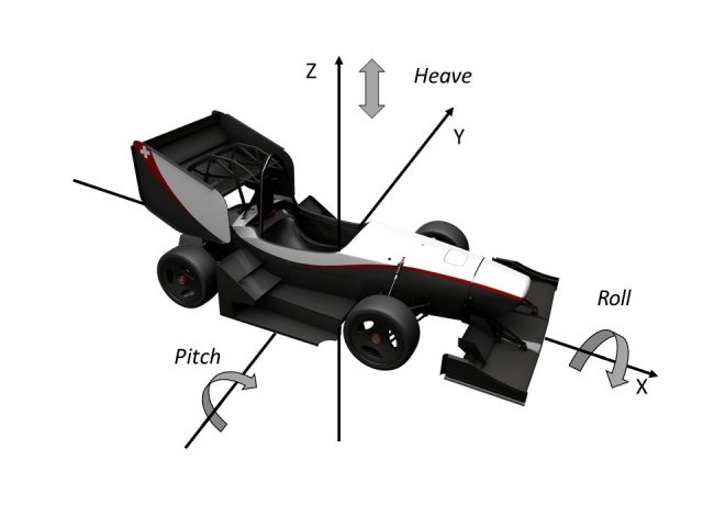
Movements of an acting suspension can be described by 4 modes: Pitch, Heave, Roll and Warp. Let’s use our imagination and assume a street bump just ahead of the front left wheel. The reaction force on the suspension will try to lift the whole chassis (heave), lift the front axle (pitch), lift both left wheels (roll), and twist the front axle relative to the rear axle (warp) – all at the same time.
© AMZ
- Pitch is induced mainly through braking and acceleration. Ideally, pitch stiffness would show an approximately linear force-displacement behavior.
- Heave results primarily from aerodynamics loads. The race engineer would want it to act progressively, i.e. increasing spring stiffness with increasing load.
- Roll typically happens while cornering. For the sake of balancing, rolling stiffness should be linear and happen symmetrically between left and right.
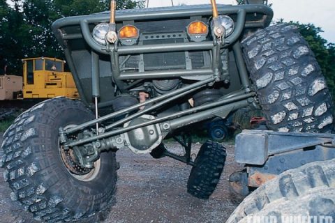
- Warp results from maneuvering and track irregularities (see illustration below). Ideally, this mode should be unsprung. This means that movements should be allowed to happen freely, without a spring or damper balancing the deformation. Of course, the tires are not rigid bodies ?.
Concept Idea
The key idea that Timothy and Alex had was to fully decouple modes. They imagined a system with 4 degrees of freedom, one for each mode, where stiffness and damping can be adjusted independently. This would simplify set-up and lower the single wheel stiffness by at least 25%. The team also could better leverage the potential of their already implemented magneto rheological fluid (MRF) dampers and integrate active suspension components.
Let’s revisit their thought process for an early stage concept. A main drawback of common suspension concepts is that decoupling of heave from pitch and roll from warp cannot be done without adding a connection between front and rear axle. Adding further rods was dismissed because of its potential added weight, the negative impact on the package, and the large number of attachment points it would require.
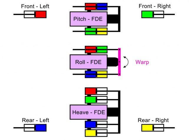
Timothy and Alex thought about various hybrid mechanical-hydraulic systems before coming up with the idea of a fully hydraulic suspension. See the illustration below and follow this link for an animated GIF.
© AMZ
Each wheel would have its own hydraulic system (see colors in the figure above). All elements that share a color would be connected to each other. Consequently, there are no connections between elements of different colors. Certainly, there would be a central unit comprised of four elements: one for each mode. Admittedly, in the figure above, there is a three-part central unit. This results from the combination of warp and roll elements through a lever arm. In an earlier concept, the central unit had different elements for roll and warp as can be seen below.
© AMZ
The warp element is a bit special. There is no spring because warp should be unsprung.
There are many added benefits of the lever arm configuration. The system is presumably lighter and allows simpler tuning of the roll balance by adjusting the length of the left and right lever arms. Roll balance can be described as a connection between roll and warp. Roll movements actuate warp and thus increase tire load on the wheels of one diagonal.
I hope you click back to the racing lounge for the second part of this story. You will read about detailed design, manufacturing and testing … and see some awesome videos of the system in action.
- Category:
- Automotive,
- Skills,
- Team achievements


Comments
To leave a comment, please click here to sign in to your MathWorks Account or create a new one.