Using AI for Reduced-Order Modeling
The following post is from Lucas Garcia, Deep Learning Product Manager at MathWorks.
This blog discusses the MathWorks’ presence at NeurIPS 2022 and my talk on ‘Using AI for Reduced-Order Modeling’ at the conference.
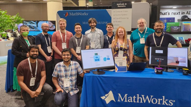
 Figure: The MathWorks team at our booth at NeurIPS 2022
Founded in 1987, the Conference on Neural Information Processing Systems (abbreviated as NeurIPS) is one of the most prestigious and competitive international conferences in machine learning. Last week, the MathWorks team was at NeurIPS 2022 in New Orleans for the in-person portion of the conference.
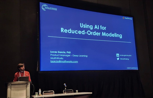
During the Expo Day at NeurIPS, I presented a talk about ‘Using AI for Reduced Order Modeling’. This blog post provides an overview of this presentation. If you are interested in learning more, check out the Slides: Using AI for Reduced-Order Modeling.
 Figure: Presentation on Using AI for Reduced-Order Modeling at NeurIPS 2022
Additionally, we had many interesting interactions at the booth on deep learning, reinforcement learning, and interoperability between MATLAB and Python®. My colleagues Drew and Naren developed an excellent reinforcement learning demo that showcases learning directly from hardware by using a Quanser QUBE™-Servo 2 and Reinforcement Learning Toolbox.
Video: Reinforcement learning demo showcasing learning directly from hardware
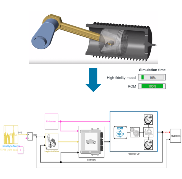
 Figure: The simulation of a reduced-order model is significantly faster than the simulation of a high-fidelity model.
Figure: AI-driven design involves data preparation, AI modeling, system design, and deployment.
Let’s take a closer look at how you can create a reduced-order model of a vehicle engine for closed-loop control of vehicle speed. In the image below, you can see a system-level model of a vehicle in Simulink. The goal is to control the vehicle’s velocity based on the driver’s input. This virtual model includes components representing a simulated driver, road conditions, the controllers, and vehicle dynamics. The passenger car subsystem models the entire vehicle dynamics: wheels, differential, vehicle body, and the vehicle engine. These have been modeled using first principles, but given the complex nature of high-fidelity models, simulation can notably be slowed down.
Figure: Replace a high-fidelity engine model with an AI-based model to reduce complexity and speed up the system simulation.
You can replace a high-fidelity model with an AI-based reduced-order model. For example, the AI model may consist of a sequence model, a Neural ODE, a Non-Linear ARX model, etc. The model should input the engine speed, the ignition timing, the throttle position, and the wastegate valve value; and output the engine torque.
The first step in the AI-driven system design workflow involves data preparation. Here, you can design a set of experiments for you to generate the required synthetic data. This can be achieved by determining which parameters to vary, running the respective simulations, and log the data you need for training.
Moving to the AI modeling phase, you can create an LSTM network programmatically with a few lines of code (for an example, see Sequence-to-One Regression Using Deep Learning) or interactively with the Deep Network Designer app. Another exciting approach involves using Neural ODEs. Neural ODEs are especially interesting when you need to model the dynamic behavior of a system, but it might not be clear how to derive the ODE from first principles. Using Neural State-Space Models, introduced in MATLAB R2022b, you can create a deep learning-based non-linear state-space model using feedforward neural networks. This allows you to train Neural ODE models without being a deep learning expert. Additionally, you can import a pretrained network from TensorFlow™, PyTorch®, or ONNX™. For more information, see Interoperability Between MATLAB, TensorFlow, PyTorch, and ONNX.
Once the model has been trained, you can simulate and test your AI model with the rest of your components in Simulink. Integrating the AI model in Simulink, couldn’t be easier. Simply drag and drop the corresponding block to your Simulink model and configure it accordingly (by specifying the location of the model or name in the workspace). By using a reduced-order model of the vehicle engine, you speed up the overall simulation time of the system:
Figure: System-level simulation of AI-based reduced-order model for vehicle speed control
Finally, you can deploy the entire plant model (Passenger Car subsystem) by generating C/C++ code and perform system-level integration and test. Hardware-in-the-Loop (HIL) serves as a final functional test of the algorithm under design before we move into final system integration. In HIL, you can generate code both for the component or algorithm you are designing (e.g., the controllers) as well as for the plant model. The plant code, which here includes the trained neural network, runs on a real-time computer; mimicking the behavior of our vehicle. The component code or the algorithm (in this case, the controller) runs on the target platform. Simulink can be used to monitor signals and adjust parameters on the deployed components.
The same techniques can be applied to a variety of systems, for example, temperature models, turbulence and combustion simulation, and estimating NOx emissions. Check out the following user stories to learn more about these applications:
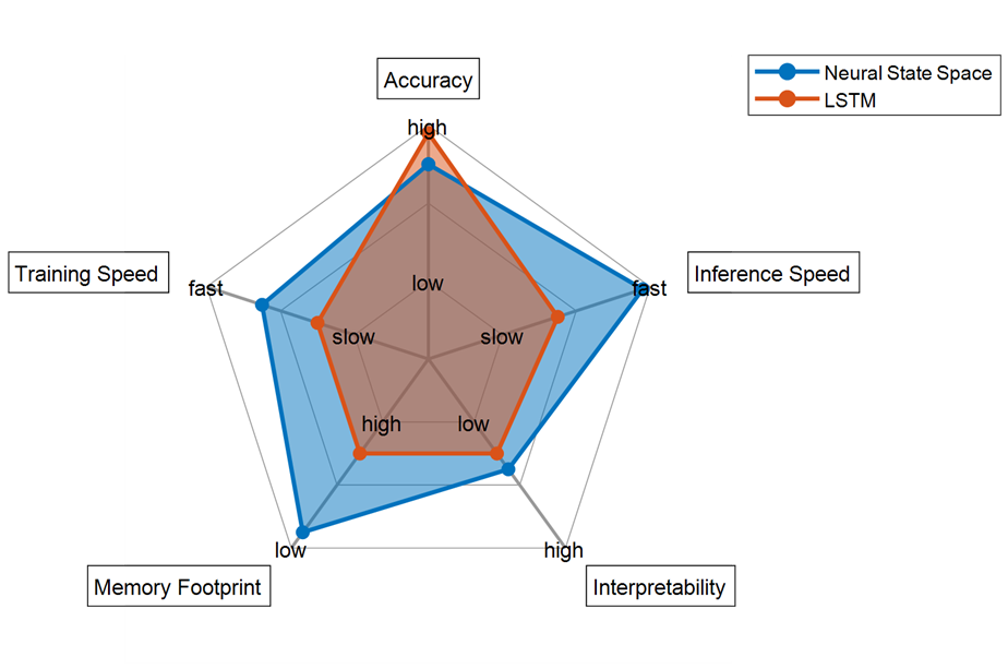
 Figure: Radar plot highlighting different attributes of the trained LSTM and Neural State Space models. Note that the results shown in this plot are specific to this vehicle engine example.
In summary, an AI model may be used to create an AI-based reduced-order model that replaces part of the complex dynamics of a vehicle engine. Using data synthetically generated from the original first-principles model, you can train AI models using various techniques (LSTMs, Neural ODEs, NLARX models, etc.) to mimic the behavior of the vehicle engine. You can then integrate such an AI model into Simulink for system-level simulation (together with the rest of the first-principles components), generate C/C++ code, and perform HIL testing.
Leave a comment with anything you’d like to chat about related to AI for Reduced Order Modeling. And don’t forget to look at the Slides: Using AI for Reduced-Order Modeling, which provide details on how to use AI for ROM at every stage of a complete system!
 Figure: The MathWorks team at our booth at NeurIPS 2022
Founded in 1987, the Conference on Neural Information Processing Systems (abbreviated as NeurIPS) is one of the most prestigious and competitive international conferences in machine learning. Last week, the MathWorks team was at NeurIPS 2022 in New Orleans for the in-person portion of the conference.
During the Expo Day at NeurIPS, I presented a talk about ‘Using AI for Reduced Order Modeling’. This blog post provides an overview of this presentation. If you are interested in learning more, check out the Slides: Using AI for Reduced-Order Modeling.
 Figure: Presentation on Using AI for Reduced-Order Modeling at NeurIPS 2022
Additionally, we had many interesting interactions at the booth on deep learning, reinforcement learning, and interoperability between MATLAB and Python®. My colleagues Drew and Naren developed an excellent reinforcement learning demo that showcases learning directly from hardware by using a Quanser QUBE™-Servo 2 and Reinforcement Learning Toolbox.
What is ROM and why use it
If you are an engineer or have ever worked in solving an engineering problem, you have probably tried to explain the behavior of a system using first principles. In such situations, you must understand the system’s physics to derive a mathematical representation. The real value of a first-principles model is that results typically have a clear, explainable physical meaning. In addition, behaviors can often be parameterized. However, high-fidelity non-linear models can take hours or even days to simulate. In fact, system analysis and design might require thousands or hundreds of thousands of model simulations to obtain meaningful results. This causes a significant computational challenge for many engineering teams. Moreover, linearizing complex models can result in high-fidelity models that do not contribute to the dynamics of interest in your application. In these situations, AI-based reduced-order models can significantly speed up simulations and analysis of higher-order large-scale systems. Reduced Order Modeling (ROM) is a technique for reducing the computational complexity or storage requirement of a computer model, while preserving the expected fidelity within a controlled error. Engineers and scientists use ROM techniques to:- Speed up system-level desktop simulation
- Perform hardware-in-the-loop testing
- Enable system-level simulation
- Develop virtual sensors and digital twins
- Perform control design
 Figure: The simulation of a reduced-order model is significantly faster than the simulation of a high-fidelity model.
AI-based reduced-order modeling
AI enables to create a model from measured data of your component, so you get the right answer in an accurate, dynamic, and low-cost way. We can’t always make good analytical models of the things in the world. Sometimes the theory and/or technology isn’t there. For example, estimating a motor’s internal temperature is challenging because no cost-efficient sensors can do this, and methods like FEA and lumped thermal models are either very slow or require domain expertise to set up. Even if you already have a high-fidelity first-principles model, you can use data-driven models to create a surrogate model that is potentially simpler and simulates faster. A faster but equally accurate model can help you progress as you design, test, and deploy your system. For this talk, I focused on replacing an existing high-fidelity first-principles model with an AI-based reduced-order model. To create such a reduced-order model, you can follow the steps in an AI-driven system design workflow: data preparation, AI modeling, system simulation, and deployment.- Virtual XCU Calibration with Neural Networks
- Building Better Engines with AI
- Using Deep Learning Networks to Estimate NOX Emissions
Conclusion
It was truly exciting to attend NeurIPS 2022 and have the opportunity to share with the Deep Learning community how AI can be used for reduced-order modeling. Before wrapping up the session, I went back to the AI-based reduced order models I had trained and analyzed different attributes. This allows you to evaluate and make design tradeoffs based on specific requirements you might have. As the following graph describes, the LSTM model provides slightly better accuracy, but the Neural State Space outperforms the LSTM in every other attribute. Figure: Radar plot highlighting different attributes of the trained LSTM and Neural State Space models. Note that the results shown in this plot are specific to this vehicle engine example.
In summary, an AI model may be used to create an AI-based reduced-order model that replaces part of the complex dynamics of a vehicle engine. Using data synthetically generated from the original first-principles model, you can train AI models using various techniques (LSTMs, Neural ODEs, NLARX models, etc.) to mimic the behavior of the vehicle engine. You can then integrate such an AI model into Simulink for system-level simulation (together with the rest of the first-principles components), generate C/C++ code, and perform HIL testing.
Leave a comment with anything you’d like to chat about related to AI for Reduced Order Modeling. And don’t forget to look at the Slides: Using AI for Reduced-Order Modeling, which provide details on how to use AI for ROM at every stage of a complete system!


Comments
To leave a comment, please click here to sign in to your MathWorks Account or create a new one.