Comparing the geometries of bwboundaries and poly2mask
MATLAB user Meshooo asked a question on MATLAB Answers about a problem with the createMask function associated with impoly. Meshooo observed a discrepancy between the output of bwboundaries and the mask created by createMask.
I want to describe the issue in more general terms here as a conflict between the geometry of the bwboundaries function and the geometry of the poly2mask function (which is used by createMask).
Here's a simple example that illustrates the discrepancy. Start by creating a small binary image.
BW = [ ...
    0 0 0 0 0 0 0 0 0
    0 0 0 0 0 0 0 0 0
    0 0 0 0 1 1 1 0 0
    0 0 1 1 1 1 1 0 0
    0 0 1 1 1 1 1 0 0
    0 0 1 1 1 1 1 0 0
    0 0 1 1 1 1 1 0 0
    0 0 1 1 0 0 0 0 0
    0 0 0 0 0 0 0 0 0
    0 0 0 0 0 0 0 0 0 ];
Call bwboundaries, which traces the perimeter pixels of all the objects (and holes) in the image.
B = bwboundaries(BW);
There's only one boundary in this case. Extract and plot it.
B = B{1};
Bx = B(:,2);
By = B(:,1);
plot(Bx,By)
axis ij
axis equal
axis([.5 9.5 .5 10.5])

If we now pass Bx and By to poly2mask, we don't get exactly the same binary mask image that we started with.
BW2 = poly2mask(Bx,By,10,9)
BW2 =

     0     0     0     0     0     0     0     0     0
     0     0     0     0     0     0     0     0     0
     0     0     0     0     0     0     0     0     0
     0     0     0     0     1     1     1     0     0
     0     0     0     1     1     1     1     0     0
     0     0     0     1     1     1     1     0     0
     0     0     0     1     1     1     1     0     0
     0     0     0     1     0     0     0     0     0
     0     0     0     0     0     0     0     0     0
     0     0     0     0     0     0     0     0     0
To understand the reason for the discrepancy, it helps to understand that bwboundaries treats the foreground pixels of the input image as points in space. Here's a plot to illustrate:
plot(Bx,By)
axis ij
axis equal
axis([.5 9.5 .5 10.5])
hold on
[yy,xx] = find(BW);
plot(xx,yy,'*')
hold off
legend('Boundary polygon','Foreground pixels')

Now let's do a plot that shows the pixels as squares of unit area. I'll include some code to overlay the pixel edges as gray lines.
imshow(BW,'InitialMagnification','fit')
hold on

x = [.5 9.5];
for k = .5:10.5
    y = [k k];
    plot(x,y,'Color',[.7 .7 .7]);
end

y = [.5 10.5];
for k = .5:9.5
    x = [k k];
    plot(x,y,'Color',[.7 .7 .7]);
end

plot(Bx,By,'r')

plot(xx,yy,'*')
hold off

Now you can see that the polygon produced by bwboundaries does not completely contain the pixels along the border of the object. In fact, most of those pixels are only half inside the polygon (or less).
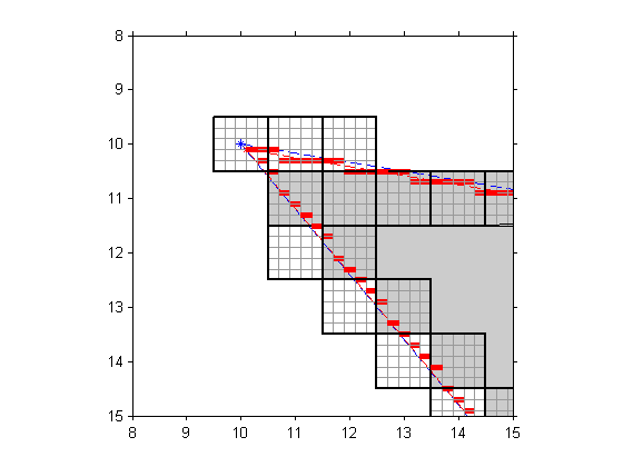
That's the clue needed to explain the discrepancy with poly2mask. That function treats images pixels not as points, but as squares having unit area. Its algorithm is carefully designed to treat partially covered pixels in a geometrically consistent way. I wrote several blog posts (POLY2MASK and ROIPOLY Part 1, Part 2, and Part 3) about this back in 2006. Here's a diagram from Part 3 that illustrates a bit of the algorithm for handling partially covered pixels.

It turns out that there is a way to get boundary polygons from bwboundaries that are consistent with the poly2mask geometry. The idea is to upsample the binary image so that the polygon produced by bwboundaries is outside the pixel centers instead of running directly through the centers.
BW3 = imresize(BW,3,'nearest');
B3 = bwboundaries(BW3);
B3 = B3{1};
Now shift and scale the polygon coordinates back into the coordinate system of the original image.
Bx = (B3(:,2) + 1)/3;
By = (B3(:,1) + 1)/3;

imshow(BW,'InitialMagnification','fit')
hold on

x = [.5 9.5];
for k = .5:10.5
    y = [k k];
    plot(x,y,'Color',[.7 .7 .7]);
end

y = [.5 10.5];
for k = .5:9.5
    x = [k k];
    plot(x,y,'Color',[.7 .7 .7]);
end

plot(Bx,By,'r')

plot(xx,yy,'*')
hold off

You can see that the pixel centers are now clearly inside the modified polygon (Bx,By). That means that when we try poly2mask again, we'll get the same mask as the original image.
BWout = poly2mask(Bx,By,10,9)
BWout =

     0     0     0     0     0     0     0     0     0
     0     0     0     0     0     0     0     0     0
     0     0     0     0     1     1     1     0     0
     0     0     1     1     1     1     1     0     0
     0     0     1     1     1     1     1     0     0
     0     0     1     1     1     1     1     0     0
     0     0     1     1     1     1     1     0     0
     0     0     1     1     0     0     0     0     0
     0     0     0     0     0     0     0     0     0
     0     0     0     0     0     0     0     0     0
isequal(BW,BWout)
ans =

     1
To everyone in the Northern Hemisphere: Happy Spring!


댓글
댓글을 남기려면 링크 를 클릭하여 MathWorks 계정에 로그인하거나 계정을 새로 만드십시오.