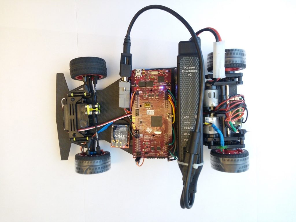
Racecar: Small – Workflow: Professional
In today’s blog post I am happy to introduce Jose Avendano Arbelaez, a first-time guest in this blog. We have been collaborating on a nice hardware-software demo including a (model) racecar.
—
This article is particularly suited for automotive student teams, but it is clearly not exclusive to them. All models related to the demo have been published on the MATLAB Central File Exchange and two instructional videos have been released: #1, #2. With this blog post, I am going to share our desired learning outcomes and some background information.
Why?
Vehicle modeling has proven to give teams a competitive advantage in student competitions. This can be combined with model-based design to simulate and prototype systems in an optimal manner. Model-based design involves stages like defining requirements, modeling the system, deploying onto microcontrollers and testing all connected through the same modeling approach. This saves time and increases the quality of the final product. We decided to show how to apply all stages of product development to reach the ready-to-race car.
Our Approach
Since we couldn’t show these features implemented on a full-size vehicle we decided to go with a small-scale version. Our RC racecar demo shows how easy it is to deploy vehicle dynamics controllers that you have previously designed and validated using Simulink. In this case, the Texas Instruments C2000 hardware support package was a good interface to the actuators and sensors that we had available in our car. MATLAB and Simulink also enable testing of our design. For this, we implemented CAN communication, a functionality of the Vehicle Network Toolbox, to both acquire data through Simulink and use the logged data directly in simulations.
Programming the ECU using Simulink Hardware Support Packages
As mentioned before, to get the Simulink model to interact with actual hardware we used the TI C2000 Support package for Embedded Coder. One of the biggest time-saving features of Simulink is that it can automatically generate code for different hardware platforms, including many low-cost solutions. For our application, the C2000 support package was fully integrated with the Texas Instruments development tools.
Making some hardware drivers using the Simulink blocks provided by the support package, meant that we could evaluate the behavior of the car in a matter of minutes. This is done by just clicking the “Build” button, and from there we could evaluate the actual car’s behavior in a matter of minutes. Check out the video for a detailed explanation of the process and the algorithms.
[VIDEO] MATLAB and Simulink Racing Lounge “Remote Control Racecar, Part 1: Programming ECUs Using Simulink Hardware Support“
Implementing the CAN Network
Other than simulations and algorithm deployment, model-based design is used for other stages of development such as testing and verification as well as validation. We decided to use the hardware to show a couple of workflows that can streamline testing and validation procedures. This meant showing how to acquire data from the car in driving tests, and showing how it can be integrated to further validation workflows. Obviously, our demo is a drastic simplification of the full programming required for a commercial vehicle. Real vehicles are mostly composed of independent modules controlling individual components such as the engine, transmission, ABS brakes, etc.
Keeping in mind scalability and relatability of the demo for an audience of automotive engineers, we decided to set up our data acquisition through a CAN network within the ECU. Showcasing the CAN devices support and how to connect to CAN from Simulink made the most sense. Teams will frequently use this type of workflow for programming the vehicle’s control modules that interfaces with the CAN network. Using Simulink supported CAN devices, e.g. allows to set up a data logger that acquires data from the car during real-time driving tests. Later, it could be replayed through a virtual CAN channel in existing simulations to perform plant validation and other analysis. For details on these implementations and more info on integrating CAN networks into simulations, check out the video below.
[VIDEO] MATLAB and Simulink Racing Lounge “Remote Control Racecar, Part 2: Integrating CAN Data into Your Simulation“
Conclusion
The main purpose of this demonstration was to show Simulink functionality that can help you to save development time, reduce overall costs and improve the performance of your designs. In this case, we moved away from simulations and showcased code generation and deployment as well as integration of CAN networks. Make sure to browse through the hardware support packages available for Simulink and MATLAB and consider using similar workflows to speed up and optimize your development efforts.
Thanks to Kvaser for providing a Kvaser Blackbird V2, which made it possible for use to show all of the functionality wirelessly. This allowed students to drive the car and experience self-tuned control algorithms.
Feel free to download the files from the File Exchange submission for details on the models and make sure to also check out this video of the car.
I hope this post gave you a good idea of the advantages of implementing model-based design on everything from small to large-scale projects and the impact it can have on easily adding or interfacing with some custom electronics. I am looking forward to any comments or interesting applications that you may have for these workflows.
— Jose


댓글
댓글을 남기려면 링크 를 클릭하여 MathWorks 계정에 로그인하거나 계정을 새로 만드십시오.