
Using Physical Modeling to Design and Simulate an Electric Vehicle
Today’s blog post is written by Veer Alakshendra, Education Technical Evangelist on the Student Competition team at MathWorks. In this blog he talks about how to model and simulate an electric vehicle using MATLAB and Simulink.
Introduction
Modeling is a way to create a virtual representation of a real-world system that includes software and hardware. It is valuable for formula student testing conditions that might be difficult to reproduce with hardware prototypes alone, especially in the early phase of the design process when hardware may not be available.
To model the electric vehicle, we will use the physical modeling approach, which is a way of modeling and simulating systems that consist of real physical components. It employs a physical network approach, where Simscape blocks correspond to physical elements, such as gears, tires, and motors.

Battery Pack
The battery pack consists of various batteries connected in series. We have modeled each battery using an equivalent circuit, which is relatively a simple electrical circuit containing a voltage source and several resistors and capacitors.

Fig 1. Cells in series
Another important step while modeling a battery is choosing the appropriate parameters of the physical blocks so that it responds as similarly as possible as a physical battery cell. One possible way to determine these parameters is by performing parameter estimation where we define the design requirements, and cost functions to optimize the model parameters. To know more about how we have used this technique to estimate the battery parameters, please check out this video titled, “Modeling Batteries Using Simulink and Simscape.”
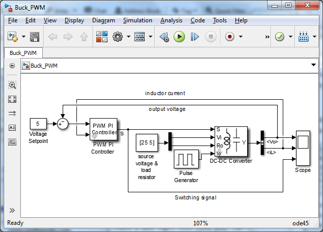
Buck Converter
To convert the high battery voltage to low voltage, we have used a DC-DC converter, specifically, a buck converter.
In this case, we have used an Average-Value DC-DC Converter block that represents a controlled average-value DC-DC converter.

Fig 2. Buck converter
Motor and Controller
The battery powers a BLDC motor and is modeled using the BLDC block available in Simscape Electrical. We have used the datasheet to set the values of the block parameters under the stator, rotor, and mechanical tabs.
To control the motor at different speeds, first, we sense the angular position using an Ideal Rotational Motion Sensor block. Further, the angular position information is used by the hall sensor to determine when the rotor transitions from one sector to another. Next, we have built a commutation logic to compute the switching pattern for the three-phase inverter.

Fig 3. Motor and controller
To learn how to design motor controllers using Simscape, refer to this video.
Transmission
The transmission consists of the following components:
- Actuator block: It converts the gear shift signal to clutch plate pressure and outputs the pressure required to engage the clutch.
- Disk friction clutch: The block restricts the transmission of torque between the driving and driven shafts.
- Gears: The gear blocks are used to build a 3-speed transmission system. We have used Simple Gear blocks with two different gear ratios to create high and low gears.

Fig. 4. Transmission
To learn more about powertrain modeling using the physical modeling approach, refer to this tutorial video.
Vehicle System
We have modeled the longitudinal vehicle dynamics using the physical blocks from Simscape Driveline which consists of the following subsystems:
- Brake: The brake is applied at the rear and front wheels. It has been modeled using the Loaded-Contact Rotational Friction block that transmits torque between two rotating surfaces.
- Vehicle: To model a two-axle vehicle body in longitudinal motion we have used the Vehicle Body block in conjunction with a set of Tire blocks.
- Sensor: The Ideal Translational Motion Sensor block measures the vehicle velocity and the distance traveled.

Fig. 5. Vehicle system
Closed Loop Vehicle Model
Finally, we connect all these subsystems through physical connections to build a closed-loop simulation model. Additionally, we have added a reference speed to be tracked and a PI controller to output the required duty cycle control signal.

Fig. 6. Closed loop vehicle model
Once we run the simulation, it is evident that the controller can reach the reference velocity of 40 km/h and drops down to zero after ~30 seconds. The sudden change in the vehicle speed accounts for the gear shift.

Fig. 7. Velocity and gear shift plot
Learning Resources
Now that you have gone through all the steps, we have followed to build the electric vehicle model, you must be wondering where you can learn more in detail. So, don’t worry! We have a proper set of tutorials to guide you to build your vehicle model.
- MATLAB Onramp
- Simulink Onramp
- Student Tutorials and Videos
- Physical Modeling Tutorial
- Motor Control Series

Fig. 8. Learning resources
Contact
Please feel free to reach out to us at racinglounge@mathworks.com in case of any queries. Also, join our MATLAB and Simulink Racing Lounge Facebook group for the latest technical articles, videos, and upcoming live sessions.
- カテゴリ:
- Automotive,
- Simscape


コメント
コメントを残すには、ここ をクリックして MathWorks アカウントにサインインするか新しい MathWorks アカウントを作成します。