In today’s blog, Abhishek Shankar will discuss how to interface with ROS2 and Gazebo to develop, test and deploy a controller for an autonomous boat using Simulink. Over to you, Abhishek…
Wave Adaptive Modular Vessel (WAM-V) is a class of surface vehicles that offer great stability and maneuverability. These vehicles were quickly adopted for research and are now widely used in a lot of maritime applications including maritime robotics competitions.
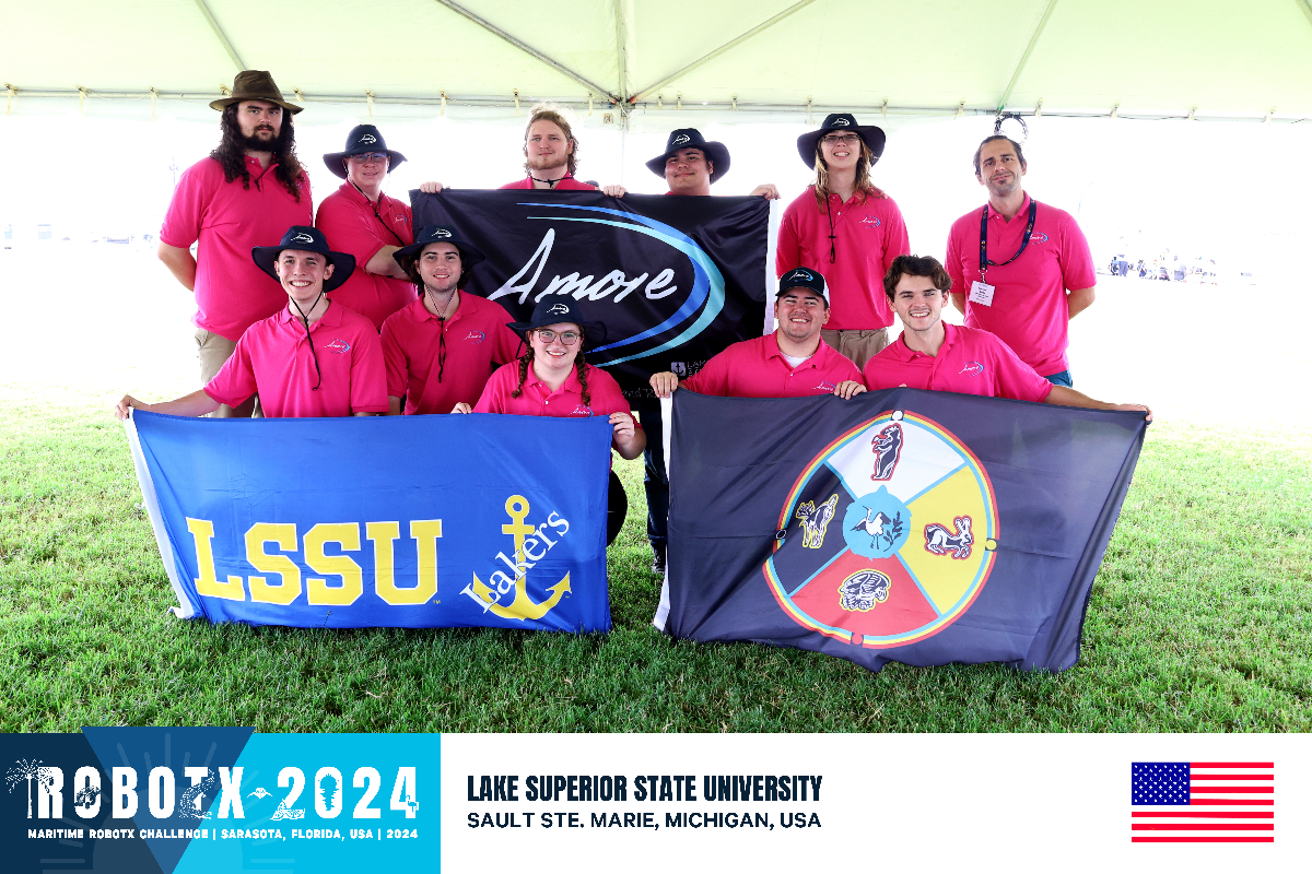
RobotX is an autonomous surface vehicle competition using WAM-V’s and is organized by RoboNation every other year. Developing and testing control algorithms for the competition is challenging due to unpredictable factors like wind, waves, and lighting. Simulation helps overcome these challenges. The Open Source Robotics Foundation (OSRF), in collaboration with the Naval Postgraduate School, has created
Virtual RobotX (VRX)– a Gazebo-based simulation environment that replicates the competition conditions. This allows teams to test and deploy various algorithms to attempt the challenges. Moreover, the simulation environment also proves to be a reliable test bed for other competitions (Njord, RoboBoat, etc.) and for researchers developing novel algorithms!

In this blog, I’ll explain how to develop and deploy a Pure Pursuit controller for the WAM-V in Simulink by interfacing with the VRX environment. Simulink facilitates development of control systems and this blog shows how to use the tools available to interactively design and deploy your controller. You can access the model from .
Connect to the simulator
To connect to the simulator and get started, follow these steps:
- Install the VRX simulator using the steps shown here. We’ll be using ROS2 to interface with the simulator but if you are using the classic version with ROS 1, a few modifications are needed, and these will be highlighted in relevant sections
- Once installed, open the simulation on your PC or virtual machine.
- Open MATLAB (ideally in a different machine)
- If both the machines are in the same subnet, you should have access to all the ROS 2 topics published. If in different subnets, create a DEFAULT_FASTRTPS_PROFILES.xml as detailed here.
- If you are using ROS 1, connecting to an external master is detailed in this blog post
- Check that you have access to the ROS topics published by running the command
7. Open WAMV-control.prj from the downloaded package, which should open the following Simulink model with access to all the ROS topics in the network.
Model Overview
The model can be broken down into 4 parts – Subscriber (Sensing), Navigation, Control and Publisher (action). The waypoints to the controller in this model are hard coded but, in a competition, or in an unknown environment, this would be provided by the path planning algorithm you use. You can take a look at different path planning algorithms
here. In the following sections, I’ll go over the details of each subsystem.
ROS Subscriber and Publisher
The subscriber takes the GPS and IMU messages from the simulator and uses it to calculate the pose of the robot (X, Y, theta).
The latitude, longitude and altitude from the GPS message is converted to an East-North-Up (ENU) coordinates using MATLAB’s
geodetic2enu function. This coordinate system is easier to work with and is often used in mobile robotics for navigation purposes. The IMU message contains orientation in quaternion values. I’m using the quaternion to rotation angle block in Simulink to convert it to Euler angles which gives us the orientation (theta) along the z-axis. These values are then fed to the controller.
The publisher sends out thrust commands for each propeller on the topics defined in the simulator. The default configuration in the VRX simulator is a propeller on the rear left and rear right and this is the configuration I’m using for the thrust calculation (details given further down). However, if you are using a different propeller configuration for your application, I’d encourage you to investigate the kinematics to calculate the appropriate thrust for the given linear and angular velocity.
Controller
The controller subsection has a few components that interact together to provide the thrust values for the vehicle. The main component is the
Pure Pursuit block which is a tracking algorithm developed by Carnegie Melon University in the early 1990’s. The algorithm computes angular and linear velocity commands that moves the robot from the current position to a goal position and as such, the inputs to the block are current pose and target location or way points. The controller lets you set the desired linear velocity and the maximum angular velocity. For this model, I’ve set the linear velocity to 0.3 m/s and maximum angular velocity to 0.4 rad/s. The main tuning property for Pure Pursuit is the look-ahead distance. Too small of a value will cause the robot to oscillate and too large of a value will make the curvature larger along corners. For this model I have set the value to 5 m. You can read more about the controller
here. One of the drawbacks of Pure Pursuit is that it does not stabilize the robot at a point so I’ve added a distance threshold of 1m, which is a simple euclidean distance calculation, and once the robot is within this threshold to the goal, the model will output 0 thrust values and stop the simulation.
With the velocities and a threshold in place, the next step is to convert these to thrust values to be published. As mentioned earlier, I am using the default two propeller configuration and modeled the kinematics as a simple linear system. This proved to work quite well for this configuration but if you are going with a different configuration, make use of the inverse kinematics to get the right values. For this configuration, I got some data (angular and linear velocity for different thrust values) and found that they were proportional (
v=α⋅T) and the proportionality constant for both are shown below.

This holds if the propeller position is fixed. The VRX simulator allows you to vary the propeller position for finer control but for this demo, the positions are fixed. To obtain angular velocity, the thrust values are modeled similar to a differential drive robot where if one propeller has a thrust of X newtons, the other will have -X newtons which provides a moment about the z-axis for the robot to turn. The calculated thrust values for linear and angular velocities are then added to get the final value. If the robot is within threshold to the goal, both the output values (left and right thrust) are set to 0.
Performance
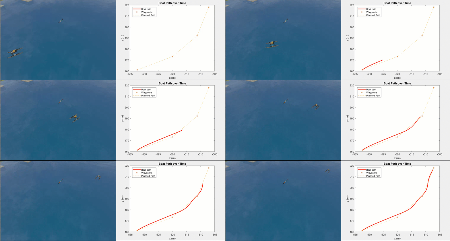
The next step in the process is evaluating the performance of the controller. Given the waypoints, we can see how closely the boat is able to track these points. Simulink lets you log signals to analyze them during and after simulation using the Simulink Data Inspector. I’ve logged the x,y points (in ENU coordinates) of the boat to visualize the performance. Controller development is often an iterative process and you’ll have to tune the parameters to get the desired performance. As mentioned before, lookAheadDistance is the main turning parameter for Pure Pursuit. The graph below shows the tracking performance for lookAheadDistance = 2.5m (yellow) and 5m (red). It is clear that 2.5 is low as the boat oscillates a lot along the planned path. In contrast, a value of 5 results in a much smoother path.

The right value for your application must be obtained iteratively and Simulink Data Analyzer makes it easier to visualize the performance and make these iterations faster. For the purpose of illustration, I have exported the logged data to the workspace. You can find the data and the script to plot in the scripts folder.
Deploy the Controller as ROS2 Node
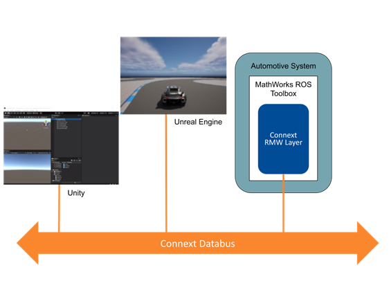
The final step after designing and tuning the controller is to generate code and deploy it to the robot or in this case the simulator. Simulink lets you do this in just a few steps. First, let’s configure the hardware properties. Since this is a ROS 2 simulation, I’m choosing ROS 2 as the target hardware (for ROS 1, change the target hardware to ROS 1) and you can set the network properties such as the IP address, username and password in the hardware tab.
The “Test” option lets you test the connection between the host PC and the machine running the simulator. This is required for Simulink to transfer the generated code and build it in the target device. If the connection is established, simply click on “Build and Run” in the tool tab to generate an executable ROS node and transfer it to the machine running the simulation. More information on code generation and deployment can be found in this
video series and
this webinar.
Conclusion
And that’s the end of the post! This blog went over developing, tuning and deploying a Pure Pursuit controller for a WAM-V in simulation. Simulink lets you easily subscribe to ROS topics, feed them to a control block and publish the relevant action messages. The workflow lets you focus on high level development and not worry about the lower level control implementation, thereby saving time and reducing errors. Additionally, you can also log signals and analyze the performance using the
Simulink Data Inspector and make the required adjustments faster. Finally, deploying the model is easy and can be done in a few minutes with guaranteed performance. You can use this workflow to deploy other controllers such as PID or MPC, just switch the pure pursuit block with the desired controller block! You could also check interesting algorithms for
path planning and
decision making that we offer. If this inspires you to work more on marine robotics, take a look at
RobotX which has a MathWorks Simulation Award introduced this year that you can participate in if you used MATLAB or Simulink for building your robot! For more information on MATLAB and Simulink and how it can be applied for robotics, check out this
web page!


コメント
コメントを残すには、ここ をクリックして MathWorks アカウントにサインインするか新しい MathWorks アカウントを作成します。