
Accelerate Aerial Autonomy with Simulink and Microsoft Project AirSim
In this blog post, we’re going to take a deep dive into a co-simulation workflow using Microsoft’s Project AirSim and MathWorks’ Simulink®. You will learn how to integrate custom vehicle dynamics models from Simulink with photorealistic 3D simulation from Project AirSim. Let’s get started!
With the rise of Advanced Air Mobility (AAM) applications, UAV use cases are expanding from last-mile delivery and inspections to logistics and flying taxis. Prior to an autonomous flight operation, Unmanned Aerial Vehicles (UAVs) go through rigorous simulation-based testing to ensure safety and efficient performance.
To test and evaluate these applications, high-fidelity dynamics models of UAVs are simulated in photorealistic 3D scenarios. UAVs involve several sensors and simulating them helps with generating synthetic data to train AI models and test autonomy algorithms.
The Integrated Workflow for Developing Autonomous Aerial Systems
Before we dive into the co-simulation example, let’s quickly go over the workflow for developing unmanned aerial systems. There are many components that come into play, including:
- Modeling the vehicle
- Developing control and autonomy algorithms
- Analyzing data
- Virtual testing with sensor models
- Connecting or deploying to hardware
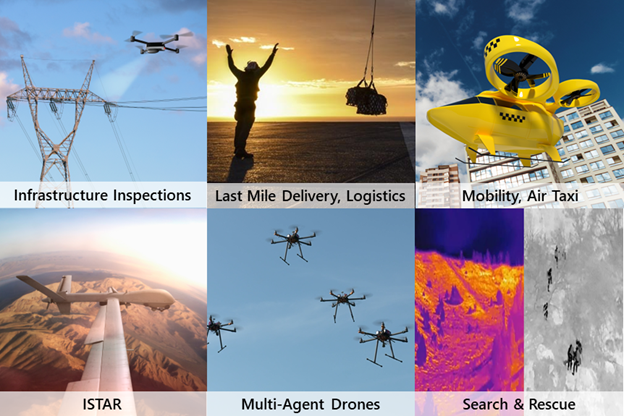
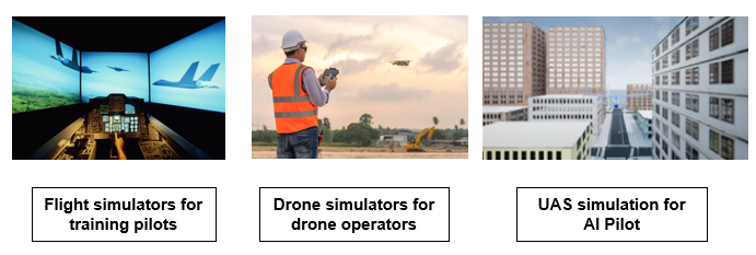
Simulink interfaces with Project AirSim to combine capabilities for UAV development in use cases such as infrastructure inspection, delivery, air taxis, inspection and recon scenarios, multi-agent drones, as well as search and rescue.
Project AirSim and Simulink Co-Simulation
What is Project AirSim?
Microsoft Project AirSim is an AI-first platform for safely creating, training, and validating autonomous agents which enables users to build autonomy solutions for UAVs in a dynamic 3D world.
Why should you integrate Simulink and Project AirSim?
An end-to-end simulation workflow requires a photorealistic 3D environment with real-world scenes and physics-based aircraft models. Further, it needs to send controller commands to the virtual aircraft and perform autonomy operations by simulating the aircraft sensors.
The Model-Based Design approach with Simulink enables engineers to efficiently develop high-fidelity physics models and control systems. It lets flight dynamics engineers build custom aircraft designs such as VTOL. See this blog to learn more about MathWorks’ solutions for UAVs.
Project AirSim provides 3D world rendering and sensor simulation with capabilities to import Bing Maps GIS data for real-world scenarios. It lets simulation engineers bring the flight dynamics to an easy-to-use simulation platform that can be scaled on the Azure cloud.
How can you connect these two platforms?
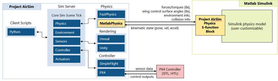
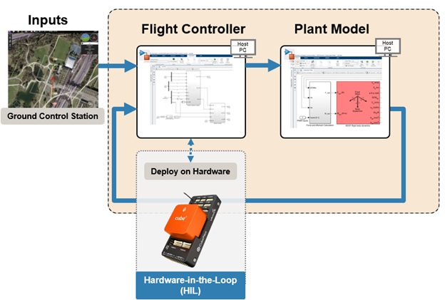
The initial integration is a Simulink S-function interface that passes physics data between Project AirSim and Simulink at every time step. This interface allows you to use a customizable Simulink dynamics model instead of the built-in simple FastPhysics model.
The data is passed over a request-response TCP connection, which could be local or remote, on either Windows or Linux. The data that’s passed includes rotor forces and torque, wing control surface angles, environment, and collision information.
The Simulink model can use this to calculate a new kinematic state for the vehicle’s pose, velocities, and accelerations, and pass that back to AirSim at each step.
Advanced Air Mobility Demo with a VTOL Aircraft
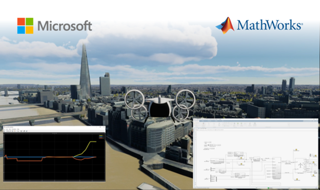
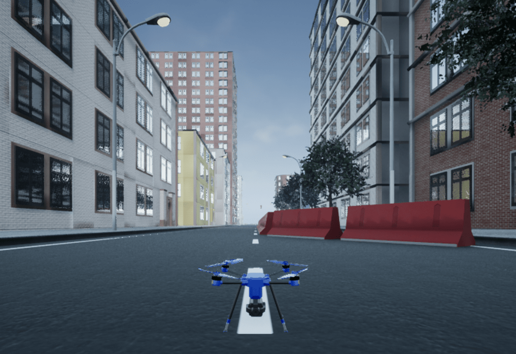
In this example, a VTOL aircraft carries out a mission in a real-world environment, showing how Simulink uses the Project AirSim S-function block to pass data signals in and out, while the visual flight instrument displays track vehicle motion. A Python client script for Project AirSim connects to the sim server and configures the scenario and vehicle to bring everything up. Once the PX4 flight controller starts running, the QGroundControl mission planner connects to it and locates the vehicle on the map based on the simulated GPS sensor data.
From there, the vehicle starts flying the mission by taking off, climbing in multirotor mode, and then starts transitioning into fixed-wing flight mode. The aircraft soars over the Texas Motor Speedway, stays on its mapped trajectory and lands safely on the pad for a successful mission completion.
In this video, we see an advanced air mobility example showing a VTOL aircraft landing after completing a mission in the Dallas Fort Worth area of Texas using AirSim and Simulink. You can see the Project AirSim simulation server on the top left screen and MATLAB and Simulink model on the top right. The Simulink model contains Project AirSim’s S-function block and an example dynamics model.
The vehicle’s motion during the flight is calculated using an example VTOL dynamics Simulink model that combines multirotor and fixed-wing forces and feeds them to a 6 degree-of-freedom dynamics block. Using Bing Maps geospatial data for the environment allows Project AirSim to switch the scenario to another area with just a scene configuration change to move the home geo-coordinate to another location’s tile set.
Summary
In this blog, we walked you through the co-simulation workflow of integrating Microsoft’s Project AirSim with Simulink. By combining these two platforms, engineers can create a simulation environment to run effective tests for UAV development including perception and autonomy algorithms. We’d love to hear about how you plan to use Project AirSim and Simulink to bring your UAV applications to reality.
Get a deeper dive to this workflow from MATLAB Expo 2023 video proceedings where Effendi Dufford and Balinder Malhi from Microsoft presented this integration alongside Fred Noto from MathWorks.
Learn more about Project AirSim and MathWorks’ UAV solutions.
- Category:
- Unmanned Aerial Vehicles


Comments
To leave a comment, please click here to sign in to your MathWorks Account or create a new one.