
Implicit Surface Intersections
Implicit Surface Intersections
We talked about implicit surfaces here back in March. Recently, there was an interesting question about them on MATLAB Answers.
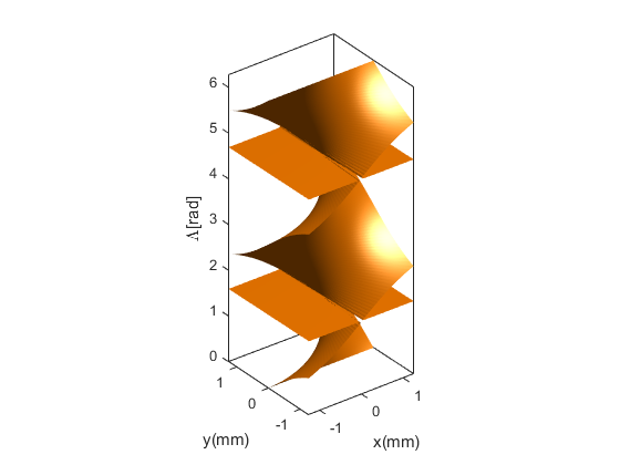
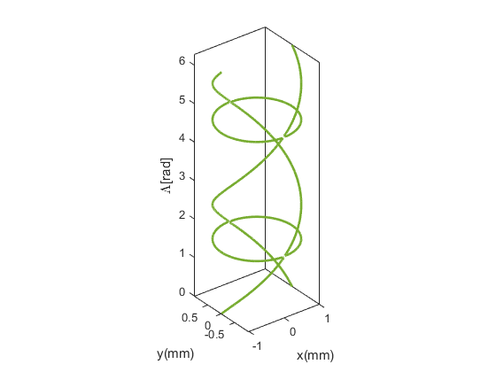
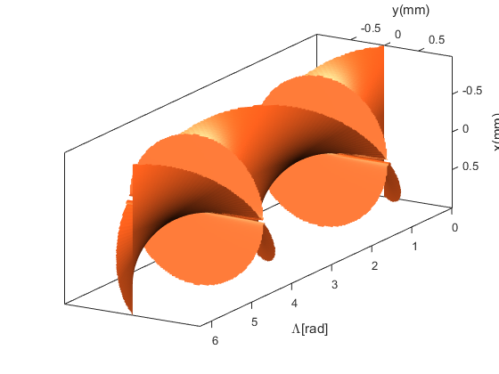
Dr. Vyas has a surface which is defined by the following equation.
$$y - x*tan(z) = 0$$
It apparently comes from a problem involving polarization of light by crystals.
He has already figured out how to compute the surface ...
[x3, y3,z3] = meshgrid(linspace(-1.25, 1.25, 150), ...
                       linspace(-1.25, 1.25, 150), ...
                       linspace(0, 2*pi, 150));
f2 = y3-x3.*tan(z3);
hel = isosurface(x3, y3, z3, f2, 0);
... and draw it using the technique we talked about in that blog post.
patch(hel,'FaceColor',[1 .5 0],'EdgeColor','none');
view(3)
camlight
ax = gca;
set(ax,'XLim',[-inf inf],'YLim',[-inf inf],'ZLim',[-inf inf],'DataAspectRatio',[1 1 1])
box on
xlabel('x(mm)')
ylabel('y(mm)')
zlabel('\Lambda[rad]')
But now he wants to compute the interesection of that surface and the cylinder defined by this equation:
$$x^2 + y^2 = 1$$
In general, computing the interestion of implicit surfaces is a fairly challenging problem. There are three basic approaches.
- Find an analytic solution for the intersection.
- Find an intersection point, and then use a tracing scheme to generate the curve.
- Calculate the intersection on the grid we're using to draw the surfaces.
The first two approaches can be fairly involved in some cases, but the third approach generally isn't too hard to implement. Let's walk through that approach in detail.
First we take the vertices we got from the isosurface, and create a logical mask of all of the vertices which are outside the cylinder. To do that, we just need to compute the radius for each vertex, and then compare that to 1.
r = sqrt(hel.vertices(:,1).^2 + hel.vertices(:,2).^2);
cylrad = 1;
mask = r>cylrad;
For each triangle, count the number of vertices which are outside the cylinder.
outcount = sum(mask(hel.faces),2);
If the number of outside vertices is 0 or 3, then we don't care about the triangle. That's because those triangles are completely inside or completely outside the cylinder. This means that they can't contribute to the intersection curve.
If the number of outside vertices is 1 or 2, then the triangle crosses the cylinder. These are the triangles we're interested in.
cross = (outcount == 2) | (outcount == 1);
crossing_tris = hel.faces(cross,:);
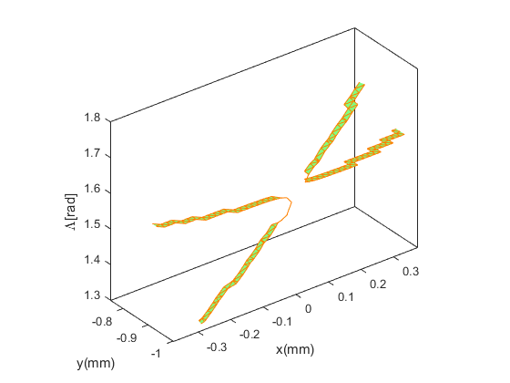
Let's take a quicky look at those triangles.
cla
ct = patch('Vertices',hel.vertices,'Faces',crossing_tris,'EdgeColor',[1 .5 0],'FaceColor',[.5 1 .5]);
That looks pretty close. If we zoom in we can see that we have a thin band of triangles which go around the part of the surface which crosses the cylinder.
xlim([-.375 .375])
ylim([-1 -.75])
zlim([1.3 1.8])
Now we need to take each of those triangles and turn it into a line segment which shows the intersection.
The math for calculating the intersection actually involves terms which cancel out so that the calculation for the 1-out and 2-out triangles look the same. So at this point we'll simplify things by flipping all of the 1-out triangles around so that they look like 2-out triangles. That way we only have to deal with one type of triangle.
out_vert = mask(crossing_tris);
flip = sum(out_vert,2) == 1;
out_vert(flip,:) = 1-out_vert(flip,:);
Here's where things get a little messy. Each row of out_vert contains one 0 and two 1's. We want to draw a line between the edges of the triangles which connect the vertex with the 0 with each of the two vertices with a 1.
I'm sure there's a cleaner way to do this, but here's what I came up with.
ntri = size(out_vert,1);
overt = zeros(ntri,3);
for i=1:ntri
    v1i = find(~out_vert(i,:));
    v2i = 1 + mod(v1i,3);
    v3i = 1 + mod(v1i+1,3);
    overt(i,:) = crossing_tris(i,[v1i v2i v3i]);
end
It's all downhill from there!
Next we need to calculate where each of those two edges of the triangle cross the cylinder.
We've already computed the radius at each vertex, so we can compute u & v parameters for linear interpolation like this:
u = (cylrad - r(overt(:,1))) ./ (r(overt(:,2)) - r(overt(:,1)));
v = (cylrad - r(overt(:,1))) ./ (r(overt(:,3)) - r(overt(:,1)));
And then use those to do the linear interpolation to compute the position where the edge crosses the cylinder like this:
uverts = repmat((1-u),[1 3]).*hel.vertices(overt(:,1),:) + repmat(u,[1 3]).*hel.vertices(overt(:,2),:);
vverts = repmat((1-v),[1 3]).*hel.vertices(overt(:,1),:) + repmat(v,[1 3]).*hel.vertices(overt(:,3),:);
Next we use the 3-row with nan trick I described in this post to convert those pairs of vertices into one line object.
x = nan(3,ntri);
x(1,:) = uverts(:,1)';
x(2,:) = vverts(:,1)';
y = nan(3,ntri);
y(1,:) = uverts(:,2)';
y(2,:) = vverts(:,2)';
z = nan(3,ntri);
z(1,:) = uverts(:,3)';
z(2,:) = vverts(:,3)';
OK, now we'll draw the resulting lines on top of the triangles we had earlier.
h = line(x(:),y(:),z(:));
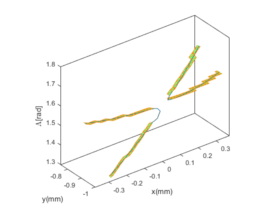
And then zoom back out.
delete(ct)
set(ax,'XLim',[-inf inf],'YLim',[-inf inf],'ZLim',[-inf inf],'DataAspectRatio',[1 1 1])
h.Color = ax.ColorOrder(5,:);
h.LineWidth = 2;
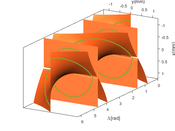
Next we can add the helical surface back in, and turn it so we can see things a little more clearly.
p = patch('Vertices',hel.vertices,'Faces',hel.faces,'EdgeColor','none');
p.FaceColor = ax.ColorOrder(2,:);
light('Position',[-7 -8 90])
light('Position',[-1 1 .25])
set(p,'SpecularStrength',.6,'DiffuseStrength',.85,'AmbientStrength',.15,'BackFaceLighting','reverselit')
set(ax,'CameraPosition',[-4 7 15],'CameraUpVector',[-1 0 0])
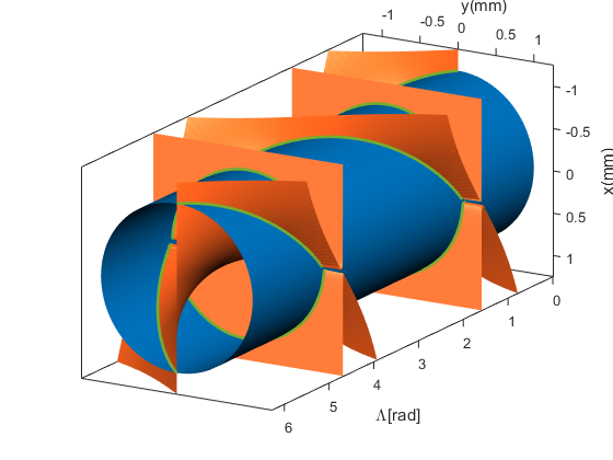
And we can add the cylinder like this:
f1 = x3.^2+y3.^2-1;
cyl = patch(isosurface(x3, y3, z3, f1, 0),'EdgeColor', 'none');
cyl.FaceColor = ax.ColorOrder(1,:);
set(cyl,'SpecularStrength',.6,'DiffuseStrength',.85,'AmbientStrength',.15,'BackFaceLighting','reverselit')
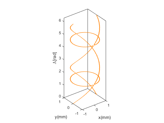
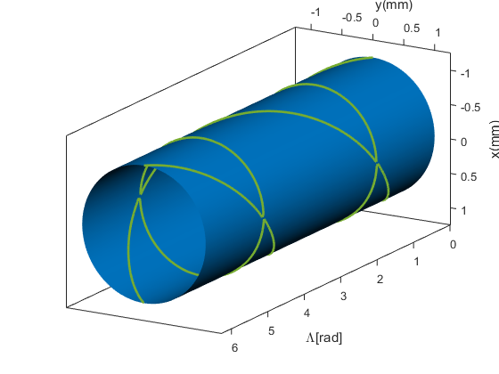
Finally, let's look at it with just the cylinder and the intersection curve.
xlim([-1.25 1.25])
ylim([-1.25 1.25])
p.Visible = 'off';
If you're working with implicit surfaces, you'll probably find that this is a useful technique to have in your toolbox. You can also modify it to do a number of other interesting things. For example, if I had just kept the triangles with a outcount of 0, I would have gotten just the portion of the surface which lies on the inside of the cylinder.
cla
ax = gca;
crossing_tris = hel.faces(outcount==0,:);
p = patch('Vertices',hel.vertices,'Faces',crossing_tris,'FaceColor',ax.ColorOrder(2,:),'EdgeColor','none');
view(3)
set(ax,'XLim',[-inf inf],'YLim',[-inf inf],'ZLim',[-inf inf],'DataAspectRatio',[1 1 1])
box on
light('Position',[-7 -8 90])
light('Position',[-1 1 .25])
set(p,'SpecularStrength',.6,'DiffuseStrength',.85,'AmbientStrength',.15,'BackFaceLighting','reverselit')
set(ax,'CameraPosition',[-4 7 15],'CameraUpVector',[-1 0 0])
xlabel('x(mm)')
ylabel('y(mm)')
zlabel('\Lambda[rad]')
To do a really nice job of this, we would need to trim the triangles which cross the cylinder. The math for that would be similar to what we did to generate those lines.
We could extend this even further and trim each of the surfaces against the other. Then we'd get the region bounded by those surfaces without any extraneous bits.
Can you think of other things you could do with this technique? Do you have some interesting implicit surfaces you could use this on? I'd love to see what you can create with it.
- Category:
- Geometry

