
Tiling Quadrilaterals
Tiling Quadrilaterals
Last time I was talking about the new pentagon tiling which was recently discovered. There are lots of other wonderful things to explore in how polygons tile the plane. One of my favorites involves quadrilaterals. They're much easier to tile than pentagons are. That's because the sum of their internal angles is 360 degrees. In fact, quadrilaterals are so easy to tile that you can make a tiling from any quadrilateral at all! Let's take a look at how that works.
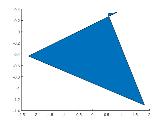
First we'll need a random quadrilateral. That's a bit trickier than you might think. We obviously want to start with 4 random points, but what order do we connect the points in? With triangles it's simple, but with quadrilaterals we need to avoid orders that have self intersections like this one:
rng default
x = randn(1,4);
y = randn(1,4);
cols = get(gca,'ColorOrder');
patch('XData',x,'YData',y,'FaceColor',cols(1,:))
We could use convhull, but that would leave out concave quads, and we're interested in them. We want to eliminate the self intersecting cases without eliminating the concave cases.
It turns out that one of the simplest ways to create a random quadrilateral in MATLAB is to create a Delaunay triangulation from the random points, and then keep 2 of the triangles. This is actually a useful technique to know because it extends to larger polygons, as you can see here.
The implementation of that (minus some coincident point error checking) looks something like this:
function [x, y] = random_quad()
  % Start with 4 random points
  x = randn(1,4);
  y = randn(1,4);
  % Triangulate them
  t = delaunayTriangulation(x',y');
  % If we found 3 triangles, throw one away
  if size(t,1) > 2
    t = triangulation(t.ConnectivityList(1:2,:),x',y');
  end
  % Return the points in the order of the boundary
  bound = freeBoundary(t);
  bound = bound(:,1);
  x = x(bound);
  y = y(bound);
Let's draw a bunch of those and see if they look nice and random.
cla
for i=1:5
    for j=1:4
        [x,y] = random_quad;
        patch('XData',x+i*4,'YData',y+j*4,'FaceColor',rand(1,3))
    end
end
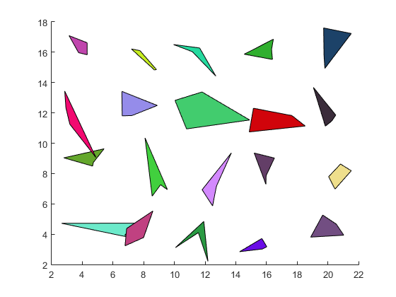
Those look pretty good, so let's pick one and see how we can tile the plane with it.
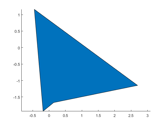
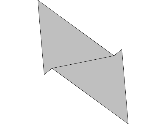
I found this one that I like the looks of, so we'll use it as for our example. But remember, this algorithm will work with any quadrilateral that doesn't self intersect.
rng(1913)
[x,y] = random_quad;

cla
axis equal
patch('XData',x,'YData',y,'FaceColor',cols(1,:))
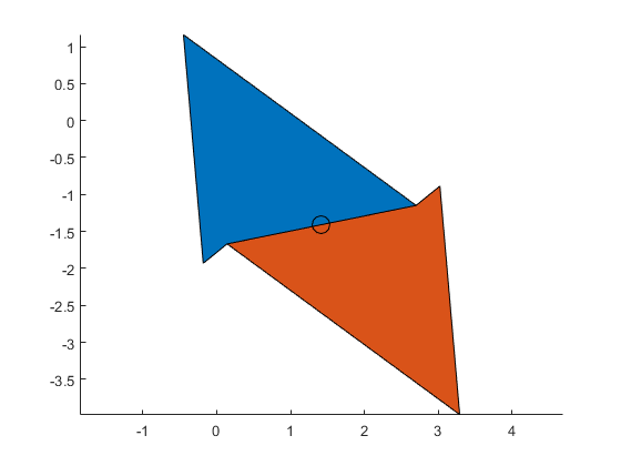
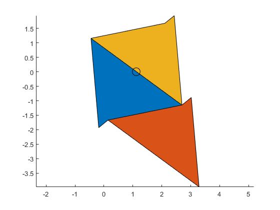
So how are we going to tile the plane with this? One thing we can see is that if we rotate a copy of it by 180 degrees around the center of one of the edges, then the two quads will line up nicely. We can use the same transform matrices we used last time.
% Points in the convenient form for transforming
pts = [x; y; ones(1,4)];

% Matrix which rotates by 180 degrees
rotmat = [-1  0 0; ...
           0 -1 0; ...
           0  0 1];

% The center of the first edge
c = pts(:,1)/2 + pts(:,2)/2;

% Rotate by 180, and translate into place
offset = rotmat*c - c;
xlatmat = [1 0 offset(1); ...
           0 1 offset(2); ...
           0 0         1];
p2 = rotmat*xlatmat*pts;

% and draw
patch('XData',p2(1,:),'YData',p2(2,:),'FaceColor',cols(2,:))
cm = line(c(1),c(2),'Color','black','Marker','o','MarkerSize',12);
And we could do the same thing around the second edge:
c = pts(:,2)/2 + pts(:,3)/2;
offset = rotmat*c - c;
xlatmat = [1 0 offset(1); ...
           0 1 offset(2); ...
           0 0         1];
p2 = rotmat*xlatmat*pts;
patch('XData',p2(1,:),'YData',p2(2,:),'FaceColor',cols(3,:))
delete(cm)
cm = line(c(1),c(2),'Color','black','Marker','o','MarkerSize',12);
... or the third edge:
c = pts(:,3)/2 + pts(:,4)/2;
offset = rotmat*c - c;
xlatmat = [1 0 offset(1); ...
           0 1 offset(2); ...
           0 0         1];
p2 = rotmat*xlatmat*pts;
patch('XData',p2(1,:),'YData',p2(2,:),'FaceColor',cols(4,:))
delete(cm)
cm = line(c(1),c(2),'Color','black','Marker','o','MarkerSize',12);
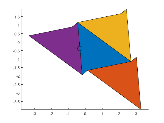
... or the fourth edge:
c = pts(:,4)/2 + pts(:,1)/2;
offset = rotmat*c - c;
xlatmat = [1 0 offset(1); ...
           0 1 offset(2); ...
           0 0         1];
p2 = rotmat*xlatmat*pts;
patch('XData',p2(1,:),'YData',p2(2,:),'FaceColor',cols(5,:))
delete(cm)
cm = line(c(1),c(2),'Color','black','Marker','o','MarkerSize',12);
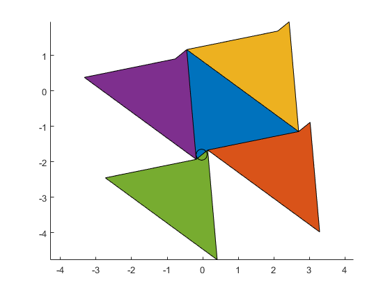
We notice a few things looking at this picture.
All four of those new copies are translations of each other, because they're all 180 degree rotations of the original.
And there appear to be gaps between them that look like the original quad.
In fact, if we do the same for any of the "other" three sides of each of those copies, we'll see that we get a translation of the original (because two rotations by 180 degrees cancel) which does tuck into one of the holes.
% Rotate around the first side again
c1 = pts(:,1)/2 + pts(:,2)/2;
offset = rotmat*c1 - c1;
xlatmat = [1 0 offset(1); ...
           0 1 offset(2); ...
           0 0         1];
p2 = rotmat*xlatmat*pts;

% And then rotate that around the second side of the result.
c2 = p2(:,2)/2 + p2(:,3)/2;
offset = rotmat*c2 - c2;
xlatmat = [1 0 offset(1); ...
           0 1 offset(2); ...
           0 0         1];
p3 = rotmat*xlatmat*p2;

delete(cm)
patch('XData',p3(1,:),'YData',p3(2,:),'FaceColor',cols(6,:))
cm = line([c1(1) c2(1)],[c1(2) c2(2)],'Color','black','LineStyle','none','Marker','o','MarkerSize',12);
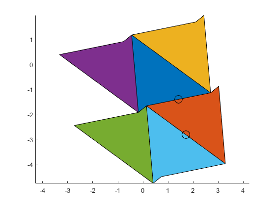
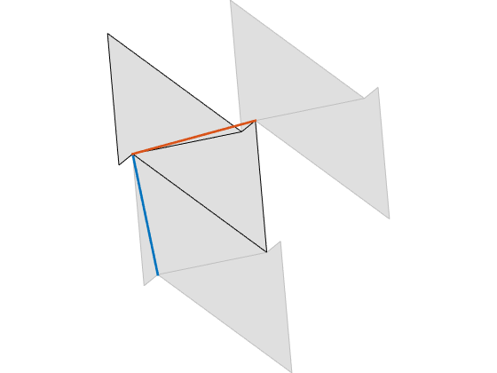
This means that fundamental region of this tiling consists of two copies of the original quadrilateral, one of which is rotated by 180 degrees, and which share one side. We can pick any two neighbors, but I'll pick the first two we drew.
cla
axis off
set(gca,'Position',[0 0 1 1])
xdata = pts(1,:);
ydata = pts(2,:);

c = [(pts(1:2,1) + pts(1:2,2))/2; 1];
offset = rotmat*c - c;
xlatmat = [1 0 offset(1); ...
           0 1 offset(2); ...
           0 0         1];
p2 = rotmat*xlatmat*pts;
xdata(2,:) = p2(1,:);
ydata(2,:) = p2(2,:);

dark = [.75 .75 .75];
light = [.875 .875 .875];
patch('XData',xdata','YData',ydata','FaceColor',dark)
And we can use these two translation vectors ...
uvec = pts(:,1) - pts(:,3);
vvec = pts(:,2) - pts(:,4);
... to assemble copies of the fundamental region into a tiling.
cla
patch('XData',xdata'+uvec(1),'YData',ydata'+uvec(2),'FaceColor',light,'EdgeColor',dark)
patch('XData',xdata'+vvec(1),'YData',ydata'+vvec(2),'FaceColor',light,'EdgeColor',dark)
patch('XData',xdata','YData',ydata','FaceColor',light)
line(pts(1,1) + [0 uvec(1)],pts(2,1) + [0 uvec(2)],'Color',cols(1,:),'LineWidth',2)
line(pts(1,1) + [0 vvec(1)],pts(2,1) + [0 vvec(2)],'Color',cols(2,:),'LineWidth',2)
And we can repeat as far as we'd like.
cla
for i=-7:7
    for j=-5:5
        ci = mod(3*j+2*i,5);
        h = patch('XData',xdata' + i*uvec(1) + j*vvec(1),'YData',ydata' + i*uvec(2) + j*vvec(2));
        h.FaceVertexCData = cols(ci+(1:2),:);
        h.FaceColor = 'flat';
    end
end
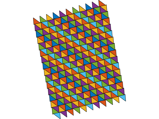
And finally, let's zoom in for a closer look.
ax = gca;
ax.Position = [0 0 1 1];
set(ax.Children,'EdgeColor','none')
ylim([-3.5 3.5])

And here are a couple more which I created with different seeds for the random number generator.


Aren't those fun? Wouldn't you like a set of tiles like that for your kitchen floor? They'd wake you up in the morning.
- 类别:
- Geometry

