
Creating Virtual Robot Environments in Simscape: Assembling Robots and Importing from CAD
For the next two blogs Jose Avendano and Matt Schafer collaborated to develop and incremental tutorial on how to use dynamic 3D simulations for robot design and programming. We will be teaching you how to setup CAD from existing robot designs into Simulink, to create virtual environments that replicate real life conditions and can be used for testing and programming of robots. By the end of these blogs you will not only be able to build the environment from scratch for the robot shown below, but you will also be able to apply these same steps to build simulations for your own robots. After reading this blog, make sure to check out part 2 here. Enjoy!
Part 1: Assembling Robots and Importing from CAD
Motivation
One of the main motivators of choosing a Model-Based Design approach in engineering is integrating design and testing to be done simultaneously through simulations. But how can you utilize this method when you are building a robot? You are probably starting with a CAD of your design and building the robot from these drawings. The natural last step is to develop a control algorithm, however testing on actual hardware can be both expensive and time consuming. What if there was a way to use simulation practices to visualize how new algorithms work instantly? What if you could even edit your CAD to see how changes in your robot design affected its performance?
This is all possible using Simulink and Simscape Multibody! Simscape Multibody is a tool from MathWorks that lets you model and simulate mechanical systems. You can import CAD files into Simscape and visualize how these files move when connected by the correct joints.
This blog is going to walk you through the steps I took to create a virtual environment for testing a robot; in this case we used the VEX V5 Clawbot as an example. There are 3 models here that you can explore while reading through this workflow. I hope you find this helpful, and please let me know what you think in the comments!
Assembling a Model in Simscape
The first step in creating a virtual environment for your robot in Simscape Multibody is to replicate your CAD assembly in Simscape.
Importing Your CAD
There are two main pathways for importing a CAD assembly into Simscape:
- Using MathWorks’ Model Import functions. This approach automates your import from some dedicated CAD programs such SolidWorks, Autodesk Inventor, PTC Creo, and Onshape. If you are just getting started on your robot CAD then consider the mates and joints guidelines for the respective import plugin, which will save you substantial time in the long run.
- Manually separate your CAD model into sub-assemblies, import them into Simscape with the ‘File Solid’ block, and use joints and ‘Rigid Transform’ blocks to connect them together. This approach is the most generic and can often result in performance improvements.
After exploring both pathways, we decided to go with option 2. Since the import tools break down the CAD models such that each part has its own solid representation in Simscape, it can result in hard to understand models. Also using the subassembly method presents a great introduction to understand Simscape Multibody block interactions if you have never used it before.
For our demonstration, we were trying to import a VEX Clawbot, and the only necessary sub-assemblies are the ones that move independently, so option 2 was simpler. The independent sub-assemblies we used are listed below:
- Chassis
- Wheels (4 of them)
- Upper Arm
- Lower Arm
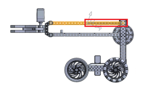
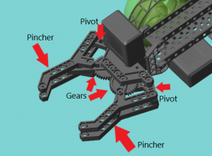
- Claw (7 independent parts)

Clawbot Claw with sub-assemblies circled
Once you have chosen these sub-assemblies, you can simplify the model by removing components that don’t have a high impact on simulation accuracy. In our case, we remove the fasteners. This is more crucial if you are trying to use the automatic import plugins since they import every part in an assembly.
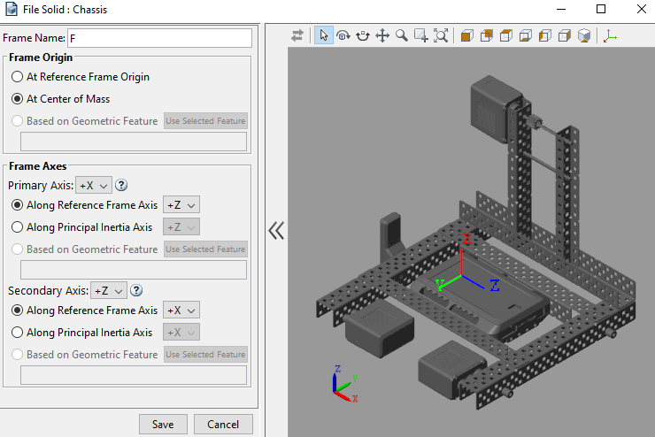
After cleaning up your CAD model, save the subassemblies as .STL files. The ‘File Solid’ block can be used to load these subassemblies into the Simulink environment. After specifying the STL file in the block, you will need to set the inertia properties of the solid. Your CAD environment should automatically calculate these inertia properties for you.
Adding Joints
After importing the STL files, you need to figure out how to link the parts together with different joints. I recommend starting out with a brief sketch of how your subassemblies are connected.
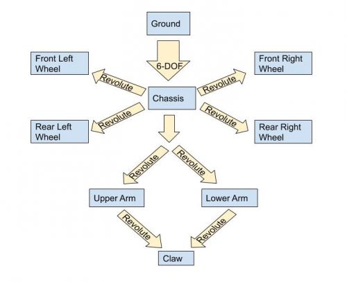
For simplicity, always choose a joint with as few degrees of freedom as possible while still allowing for the desired motion. In the case of this model, that means we primarily use Revolute Joints.
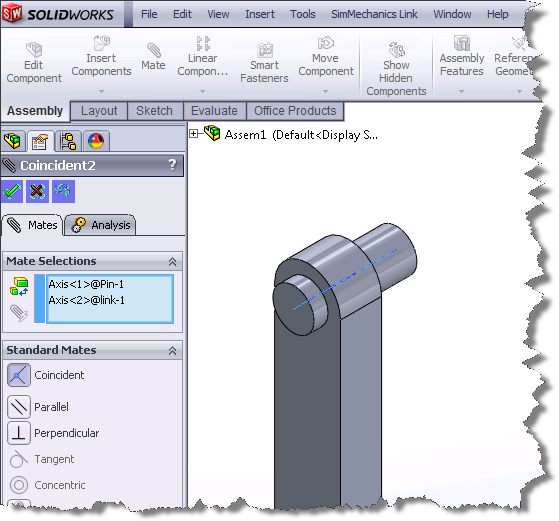
Here is what a simple joint between the chassis and front left wheel looks like:
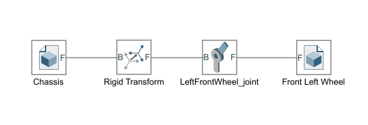
The Rigid Transform blocks are used to shift the joint and wheel center of mass to the correct location. You can use the built-in measuring tools in your CAD software to find the location of each part relative to each other.
One of the problems I struggled with the most was rotating the reference frames so that the revolute joints would work as expected. All joints in Simulink that allow for rotation are relative to the Z axis. I found that the easiest way to do this was to manually change the axis in the file solid block as shown below:
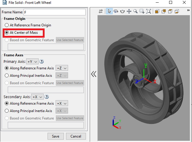
*Note that this change means that you also need to change the rigid transform block values. The translation array in this case will be [z,-y,x].
With only File Solid and Rigid Transform blocks, you could find each part’s location relative to the Chassis and arrange all the parts together to create the full robot. However, for some parts, the correct joint locations are not at the part’s center of mass and require using an extra rigid transform block to shift the joint along the part. I will walk you through examples of how to do this below.
Selecting Joint Locations
Method 1: CAD analysis
In most CAD software, you can snap directly to the part’s center of mass and measure the distance from the center of mass to any other point on the part.
Creating a joint in Simscape for the arm looks like this:
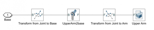
Here we use two rigid transform blocks to shift the joint to the correct location. The offset in the “Transform from Joint to Arm” block is pulled directly from the CAD measurement between the arm center of mass and the joint. Now let’s look at the “Transform from Joint to Base” block.
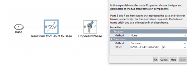
Using the steps outlined earlier, we get that the offset between the arm center of mass and chassis origin is [6.966 1.483 4.539]. We then need to shift to the actual location of the joint by subtracting the distance from the center of mass to the joint [-.1 6.0 0].
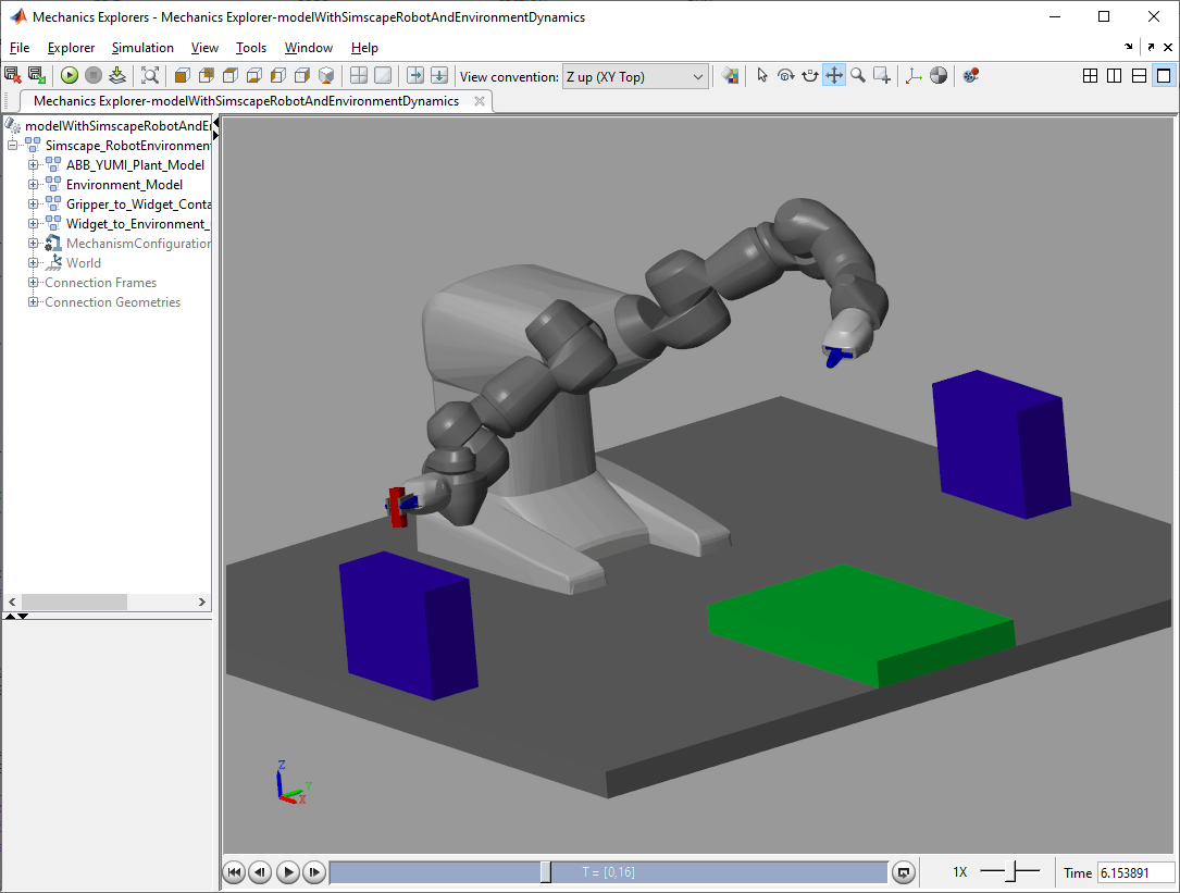
The Mechanics Explorer is your best friend when creating Simscape Multibody assemblies. After you compile the model, you can see that the joint is now located in the correct location and is attached to both the chassis and the upper arm. Use the mechanics explorer to verify part locations and even make minor position adjustments.
*Note: in order for the model to compile, you will first need to connect the Solver Configuration, World Frame, and Mechanism Configuration blocks to the robot chassis. Later on, we will move these blocks so they are connected to the playing field instead.

Method 2: Visual Inspection
In some situations, you’re better off using approximate measurements derived from more practical methods. A good example of this is the claw. The claw is made up of 6 moving parts that are attached to the claw mount.
In Simscape I divided this into 2 subsystems, one for each half of the claw. Below is what the right half of the claw looks like:
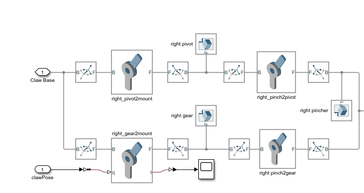
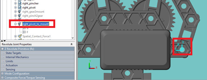
Figuring out how to put all these parts and joints in the correct locations was a bit overwhelming at first, but if we break it down, it turns out to be simple. Let’s start by examining the ‘right pivot’ connections.
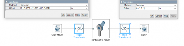
In CAD, we find the distance between the right pivot center of mass and the claw base center of mass. However, if we are not working only with CAD, we could have just as easily measured points of interest in the actual hardware. Remember to use the rotation option to make sure the Z-axis is also the axis of rotation. Next, add a revolute joint and another rigid transform block with a [0 0 0] offset.
The joint is now attached to the right pivot center of mass. You can see this by compiling the model and navigating to the joint in the Mechanics Explorer:
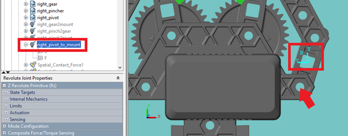
We also see that the frame for the joint needs to be shifted in the negative x and positive y direction to get to where we want it to bet (the red arrow). We then iterate through different x and y offset values until we see the correct location. If you know the length of a part, you can also just as easily derive the required offsets.
Thanks for staying with us so far! If you have followed similar steps for your own robot design, you should now have a fully assembled representation of your design in the Simscape Mechanics Explorer that accounts for the weights and inertia of all your components. In the next part of this blog post we will discuss how to add forces and torques that will affect the robot movements, and how to add more parts to create a complete virtual testing environment; check out part 2 here. Remember to download the models shown here, and if you are interested in exploring more physical modeling examples and prebuilt models, check out all the examples for Simscape Multibody.
As a bonus, here is a quick recap of tips from this post for when you are importing your own robots:
Importing CAD
- Remove extraneous parts from you CAD (such as fasteners) to simplify the import process.
- Break up your CAD model into separate parts that need to move relative to each other. Use File Solid blocks to import each part into the Simscape Environment.
- Find each part’s inertia properties from your CAD software and set those for each part.
Adding joints
- Setting the reference frame origin for each part to be the Center of Mass is helpful since you can usually snap to a part’s Center of Mass in CAD.
- All rotations must be with respect to the Z-axis.
- Use your CAD software to find the distance between the Center of Mass of different parts.
- If the joint is not at a part’s Center of Mass (ex: the arms) you must place rigid transform blocks on either side of the joint blocks.


댓글
댓글을 남기려면 링크 를 클릭하여 MathWorks 계정에 로그인하거나 계정을 새로 만드십시오.