
Requirements Verification and Validation for an Autonomous Driving Scenario
In today’s post, Akshra Ramakrishnan will talk about how to write functional requirements for a driving scenario made in Driving Scenario Designer, and write test cases to verify and validate these requirements. Over to you, Akshra..
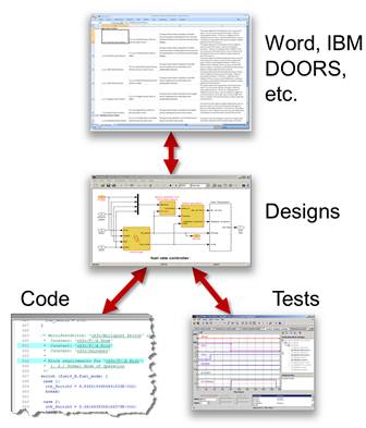
In a model-based design workflow, verification and validation against a set of requirements is integral for successful system development and deployment. This ensures that your system design meets team-defined requirements, is compliant with team standards, and is free of run-time errors.
Requirements Toolbox™ lets you author, import, and validate requirements within MATLAB® and Simulink®, track their implementation and verification status, and trace them to the source blocks. You can use Simulink® Test™ to author, manage, and execute tests for Simulink models. The Test Manager provides an interactive way to author tests from scratch, import existing test data and harness models, and organize your tests. You can also link requirements to test cases.
In this blog, I will create and link requirements for a Driving Scenario Designer scenario, and author test cases to verify those requirements.
Scenario and Model Overview:
The scenario that I will be using and writing requirements for contains one ego vehicle, a right turn, one traffic light and one stop sign. The ego vehicle’s path is pre-defined.
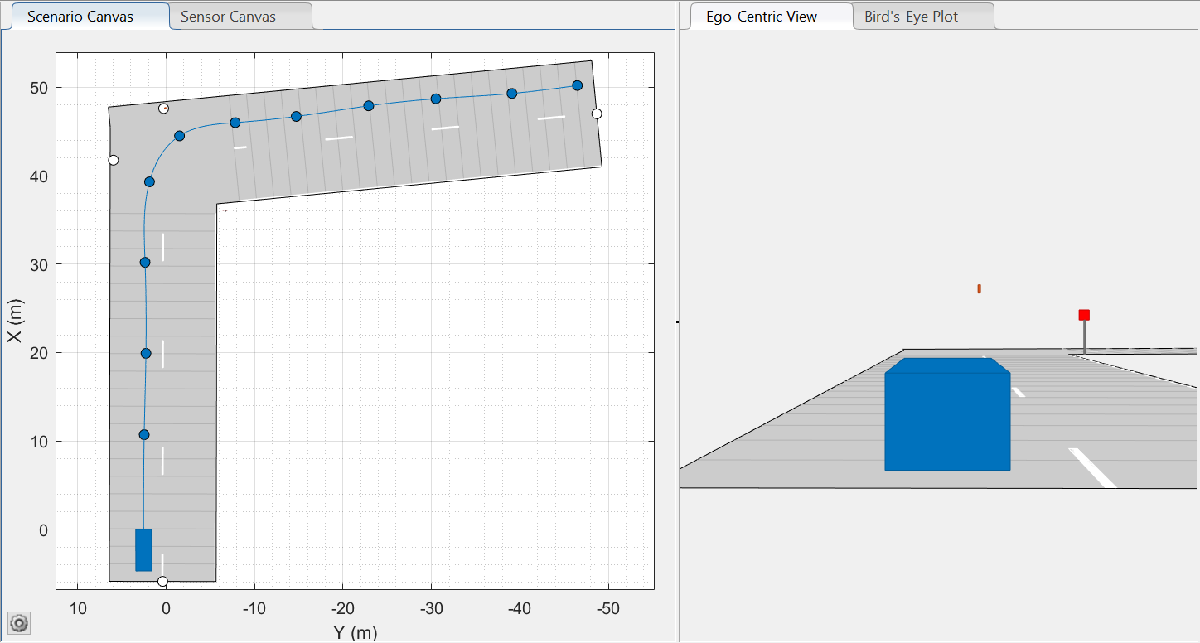
Figure 1: DSD scenario with 1 traffic light and 1 stop sign
The Simulink model I will be using contains the following subsystems
- Vehicle Dynamics: contains the vehicle dynamics model for a chosen vehicle. This subsystem outputs the ego vehicle states (position, velocity, acceleration, orientation, and angular velocity).
- Scenario ground truth: contains the scenario ground truth information for the chosen scenario. This includes the scenario reader block which takes a Driving Scenario Designer file as input and outputs the actor poses and lane boundaries. This subsystem also contains a couple of transformation blocks that perform the required coordinate and unit transformation.
- Requirements: This subsystem contains a custom block that reads all the traffic lights and stop signs actor ID from the workspace. Requirements written will be linked to this block.
- Traffic lights and signs: This subsystem contains the traffic light sensor block which hosts a Stateflow chart that assigns traffic light states (colors) to all the traffic lights in the scenario. Traffic light states are then passed to a function block that maps them to the correct traffic light ID. This outputs a bus that contains traffic light states, ID, and positions for each traffic light in the scenario. Another function block does the same for stop signs, minus the states.
- Visualization: The visualization block provides a 2D visualization of the scenario, ego vehicle path, traffic light positions and states, and stop sign positions.
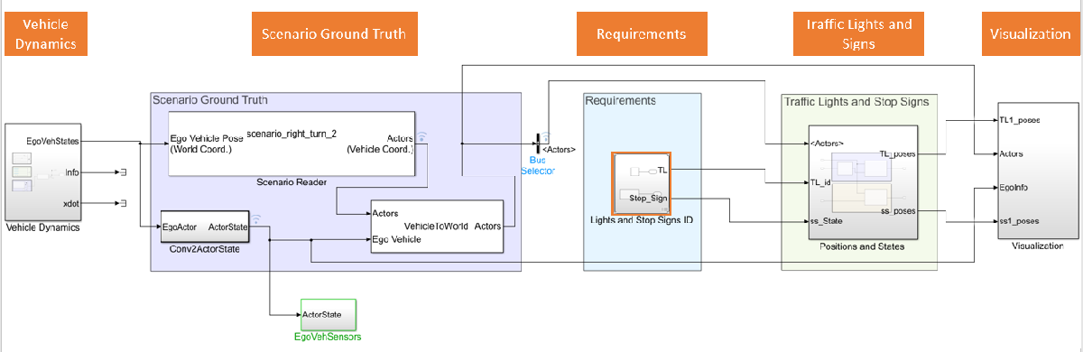
Figure 2: Simulink model overview
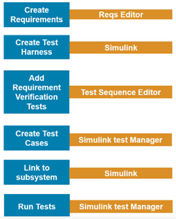
Adding Requirements Using Requirements Editor
This section shows how to define system requirements, and add requirements to a block.
Step 1: Define the system requirements
When following a model-based-design workflow, the first step is always specifying the system requirements. This ensures that all members of your team are on the same page regarding system design goals for the year. For an autonomous system, this can range from sensor specifications (field of view (FOV), range etc.), ego vehicle maximum speed limitations, system performance targets to scenario variation requirements.
In this example, I am defining two simple scenario requirements:
- The number of traffic lights in the scenario is 1
- The number of stop signs in the scenario is 1
Step 2: Add requirements to a block
Select the required Simulink block (Lights and Stop Signs ID). Open ‘requirements editor’ in the ‘Apps’ tab –> Select ‘New Requirements Set –> Give a file name. This creates a .slreqx file which shows up in the requirements editor. You can add multiple requirements under a requirements set. I’m adding the previously mentioned two requirements to this set, with their requirement IDs 1 and 2.
Test Case Verification using Simulink Test Manager
Once requirements are added, test cases must be written to verify these requirements.
Step 3: Add test cases to a test suite
Open ‘Simulink Test Manager’ from Simulink Apps –> New test suite –> Give a file name. More information about Simulink Test Manager can be found here. I will be creating two test cases TL and SS inside a test suite: one will link to requirement ID #1 and the other to requirement ID #2. Provide the name of your Simulink model, along with a test harness model.
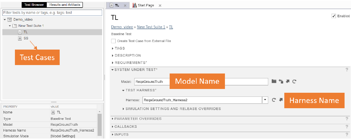
Figure 4: Simulink Test Manager
Step 3.1: Create a test harness
A test harness is a test-specific simulation environment. You can insolate blocks for unit testing, add verification logic, and test parts of your model before you make changes to the final model. I will be adding 2 test assessment blocks to verify my two requirements.
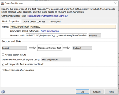
Figure 5: Creating a test harness
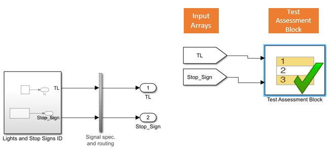
Figure 6: External test harness with test assessment block
Step 3.2: Adding verification logic
In a test case, you can:
- Compare simulation output to baseline data
- Compare the output if two simulations
- Post-process simulation output using a custom script
- Run-time assessments
In a test harness or model, you can:
- Verify logical conditions in run-time using a verify statement, which returns a pass, fail, or untested result for each time step.
- Use assert statements to stop simulation on a failure.
- Use blocks from the Model Verification or Simulink® Design Verifier™ library.
More detailed information on authoring test cases can be found here. For this model, I will be performing run-time assessments of test cases using verify statements. Add a test assessment block inside the test harness (automatically added in the previous step through a check box). I want to verify that the following criteria are met when time=0, and output that the requirement has been met once passed.
- Number of traffic lights is 1
- Number of stop signs is 1
I only have one step – the verification step. I’m checking the number of elements in the arrays ‘TL’ and ‘Stop_Sign’ (these arrays contain the IDs of all the traffic lights and stop signs in a scenario and is given as input to the ‘Lights and Stop Signs ID’ block). Add the following lines in the ‘Test Sequence’ Editor.
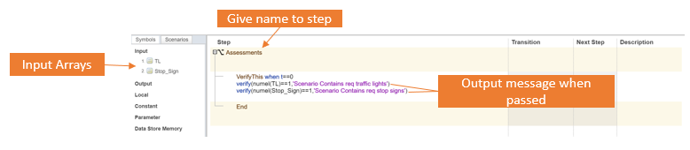
Figure 7: Test sequence editor
Step 4: Link requirements to test case
I need to add my first requirement to the created ‘TL’ test case in the current test suite.
Select ‘Requirements’ in Test Manager –> Add –> New Requirement –> Document type as Requirement Set -> Select previously saved requirement set .slreqx file –> Provide requirement ID.
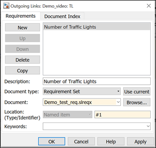
Figure 9: Add requirement to test case
In order to link the requirement to the test case, right click on the block –> Requirements –> Link to current test case. Make sure the required test case is selected in the test manager before linking.
Create the ‘SS’ test case to the test suite and add requirement #2 to it. The test harness created in Step 3.1 has verification logic for both the requirements, hence can be specified for both the ‘TL’ and ‘SS’ test cases. Follow the steps for adding and linking requirement to a test case.
Step 5: Link requirements to subsystem
In the requirements editor, select requirement –> Right click –>Link from subsystem. This makes sure that subsystems and test cases are correctly linked to the requirements and can be navigated form the requirements editor.
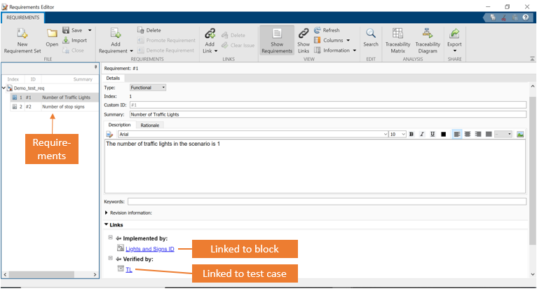
Figure 10: Linking requirements to block and test case
The requirements editor now contains the test suite with two requirements. These are linked to a block and verified by a test case.
Step 6: Verification and implementation
Right click on the requirements in the Simulink requirement view –> Check implementation and verification. This adds two tabs that show the status of that requirement.
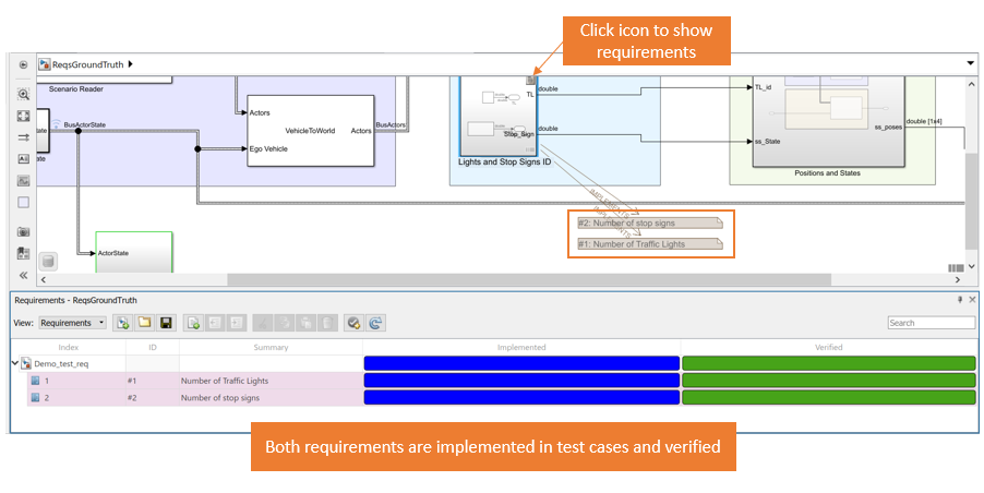
In order to run all the test cases and generate a test report, go to Test manager –> Test browser –> Check generate test report. Here you can select and fill in information that you want in your test report. Run all the test cases.
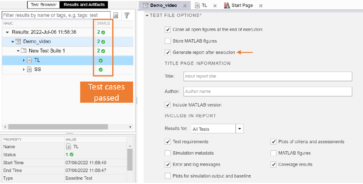
The green check marks show which requirements passed which test case. The generated test report has all this information, along with plots on the status of requirements in each timestep.
Summary
In conclusion, we saw how to write requirements for a DSD scenario using requirements editor, create test cases using Simulink test, create test harness for requirements verification, and verify and validate requirements for all the test cases inside a test suite.
Learning Resources
In case of any queries related to this blog please feel free to reach out to us at racinglounge@mathworks.com.
- 범주:
- Automotive


댓글
댓글을 남기려면 링크 를 클릭하여 MathWorks 계정에 로그인하거나 계정을 새로 만드십시오.