
How Team Endurance Racing Engineered a Winning Electric BAJA Powertrain Model in Simscape
In today’s blog, we are joined by Team Endurance Racing from Vishwakarma Institute of Technology, Pune, who placed 1st in the BAJA SAEINDIA: MathWorks Electric Powertrain Simulation Challenge 2026.
Who We Are and What We Achieved
We are Team Endurance Racing from Vishwakarma Institute of Technology, Pune, a student motorsports team focused on electric mobility and system-level vehicle engineering. At eBAJA SAEINDIA 2026, we secured an Overall 5th Rank and achieved 1st Rank in the BAJA SAEINDIA: MathWorks Electric Powertrain Simulation Challenge 2026. This blog presents our approach to the simulation challenge, covering our modeling assumptions, battery pack development, powertrain subsystem implementation, simulation scenarios, and the key engineering insights we gained.
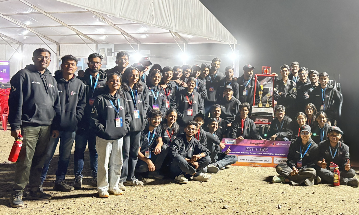
Team Endurance Racing with the Winning Car
Understanding the Problem Statement
The BAJA SAEINDIA: MathWorks Electric Powertrain Simulation Challenge 2026 required teams to simulate and analyze an electric powertrain for an all-terrain vehicle (eBAJA) using MATLAB and Simulink. A reference Simscape™ model of a generic electric ATV was provided as the starting point, and teams were expected to adapt it to align with their own competition vehicle concepts.
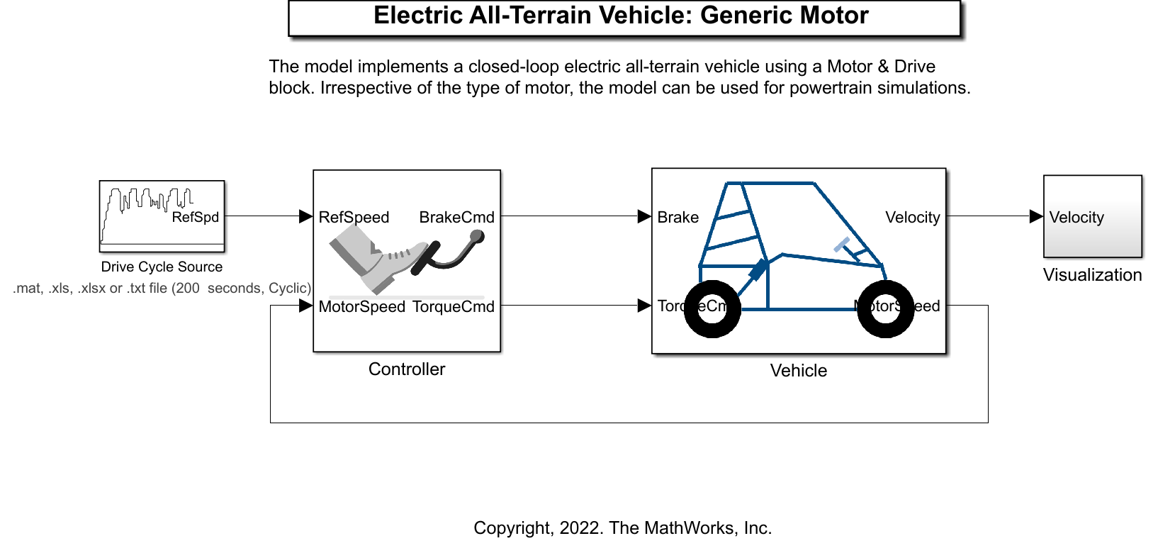
Figure 1: Reference electric BAJA model
The reference model simulated a basic electric ATV with a battery, single-motor rear-wheel drive, and a set drive cycle for performance testing. However, it lacked the actual architecture, battery setup, and specific performance details of a real BAJA electric vehicle.
The main gaps between the template model and a real eBAJA vehicle were:
– The battery was modeled as a simplified source rather than a structured pack with series-parallel cells and realistic voltage/current behavior.
– The powertrain architecture and parameters were generic and not tuned to any specific team vehicle.
– Model fidelity was limited for tasks such as realistic range estimation, transient response analysis, and component sizing.
The engineering intent of the challenge was to encourage teams to improve model fidelity by implementing a realistic battery configuration, refining the powertrain to match their design intent, and achieving accurate tracking of the prescribed drive cycle. Simulation accuracy directly affects real vehicle design because it allows teams to evaluate energy usage, thermal and electrical loading, and performance trade-offs before making hardware decisions.
Vehicle & Powertrain Assumptions
The simulated vehicle represents an electric BAJA all-terrain vehicle (eBAJA ATV) intended for off-road endurance and dynamic events. To keep the model generally applicable while still realistic, we used generic but representative parameter values within realistic bounds.
Key assumptions used in the model include:
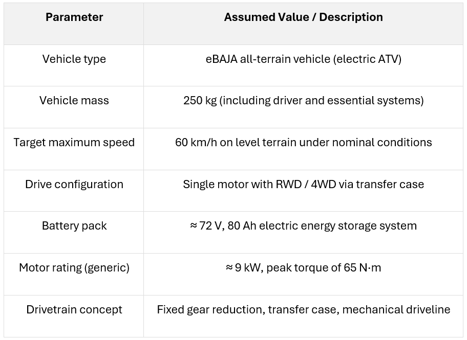
Conceptually, the fixed gear ratio and transfer case are chosen such that the motor can operate in an efficient speed range near its rated speed when the vehicle is around the 60 km/h target, while still providing adequate wheel torque at lower speeds for launch and off‑road operation in both RWD and 4WD modes.
Battery Pack Modelling Approach
The default battery block in the reference model acted as a simplified equivalent source and did not represent the internal structure, voltage behaviour, or realistic current limits of an eBAJA battery pack. This limited the ability to study cell‑level effects, voltage sag under load, and SOC evolution during transient events such as acceleration and hill climbs.
To address this, we used the Battery Builder app to create Simscape battery models with a nominal voltage of about 72 V and a usable capacity of 80 Ah, representative of an eBAJA‑level system. Voltage and capacity values were selected to support endurance‑style operation while maintaining reasonable weight and packaging for an off‑road ATV. The pack was based on cylindrical lithium‑ion cells with the following representative specification:
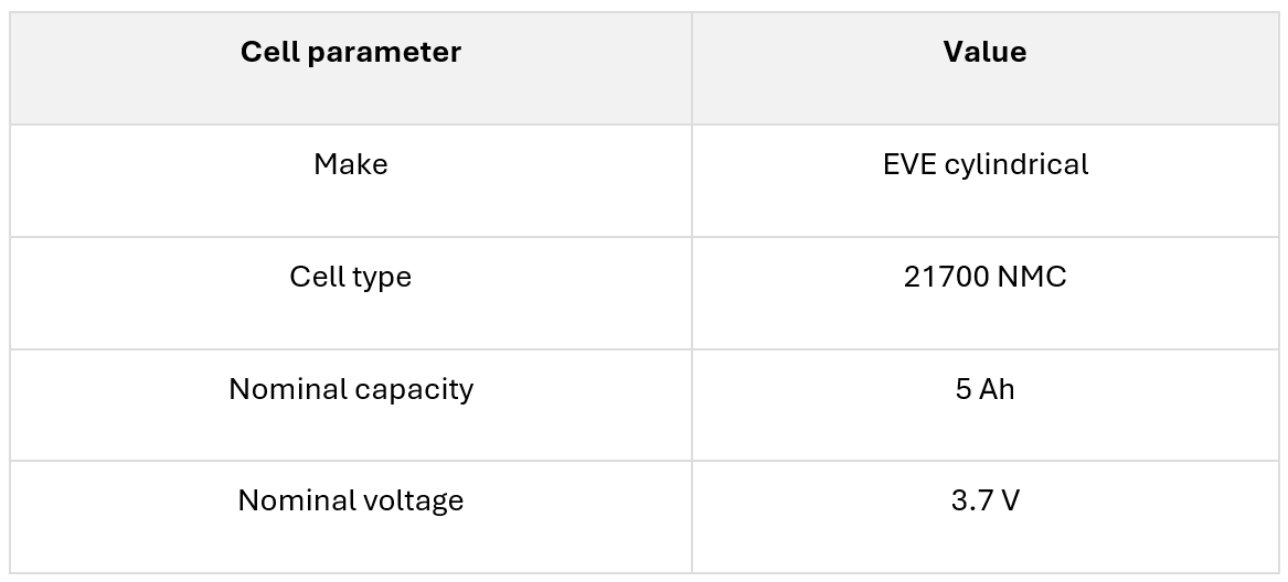
Key parameters emphasized in the battery model included:
- State of Charge (SOC) estimation using current integration (coulomb counting).
- Current limits to capture behaviour during peak load conditions.
- SOC‑dependent internal resistance to model voltage drop (sag) at higher currents.
- Monitoring of terminal voltage at pack or module level to ensure it remained within safe operating limits.
By incorporating SOC‑dependent open‑circuit voltage and internal resistance behaviour, the battery model produced realistic voltage responses during high‑demand segments, which directly influenced available motor torque and overall vehicle response.
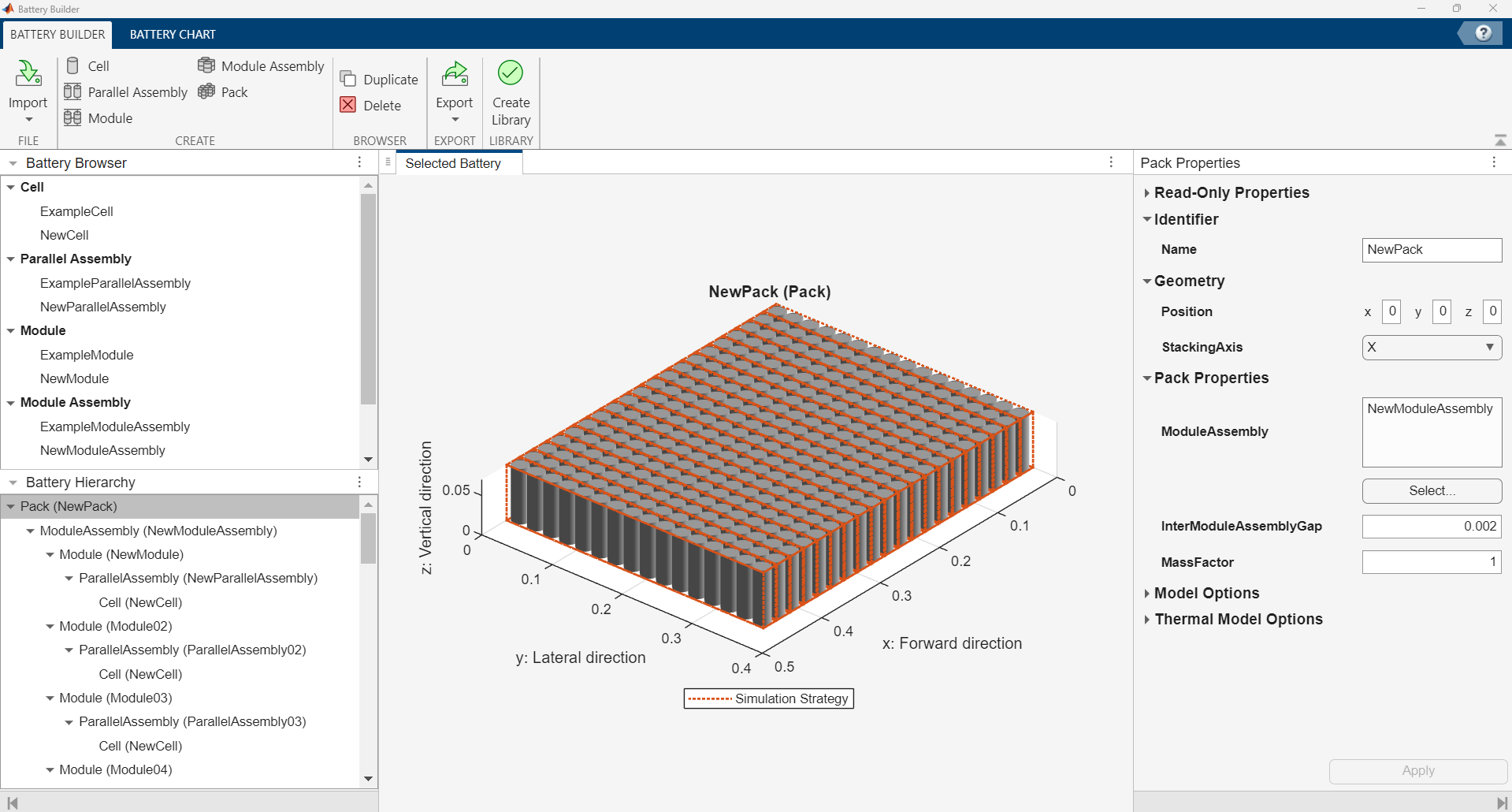
Figure 2: Battery pack
Motor Parameter Updates
The design retained the single-motor architecture but updated several key motor-related parameters to accurately represent a typical eBAJA-class traction motor. The model included the following specifications:
- A fixed gear ratio of 5, selected to provide a suitable reduction for off-road operation.
- Maximum torque set at approximately 65 N·m.
- Maximum power specified around 9 kW.
- An overall efficiency estimated at 95%.
- An efficient operating point defined at 5500 rpm with a torque output of 18 N·m.
These calibrated parameters allowed the generic motor to emulate the behavior of a realistic eBAJA traction unit while maintaining compatibility with the DC bus voltage and the overall template architecture.
Controller Tuning and Strategy
After updating the motor parameters, the control strategy was refined to ensure stable torque delivery and precise tracking of the drive cycle. Tuning efforts were concentrated on achieving smooth acceleration without oscillations, maintaining stable velocity tracking across varying load conditions, limiting peak current during periods of high demand, and preventing abrupt torque transitions that might result in unrealistic acceleration spikes.
Subsystem Interaction and Simulation Flow
The simulation established a clear chain of subsystem interaction: the battery supplied DC power to the motor drive; the drive commanded motor torque in response to torque inputs; the motor transferred this torque through the fixed gear reduction and driveline to the wheels; and the resulting vehicle speed and acceleration were fed back to the controller for closed-loop regulation.
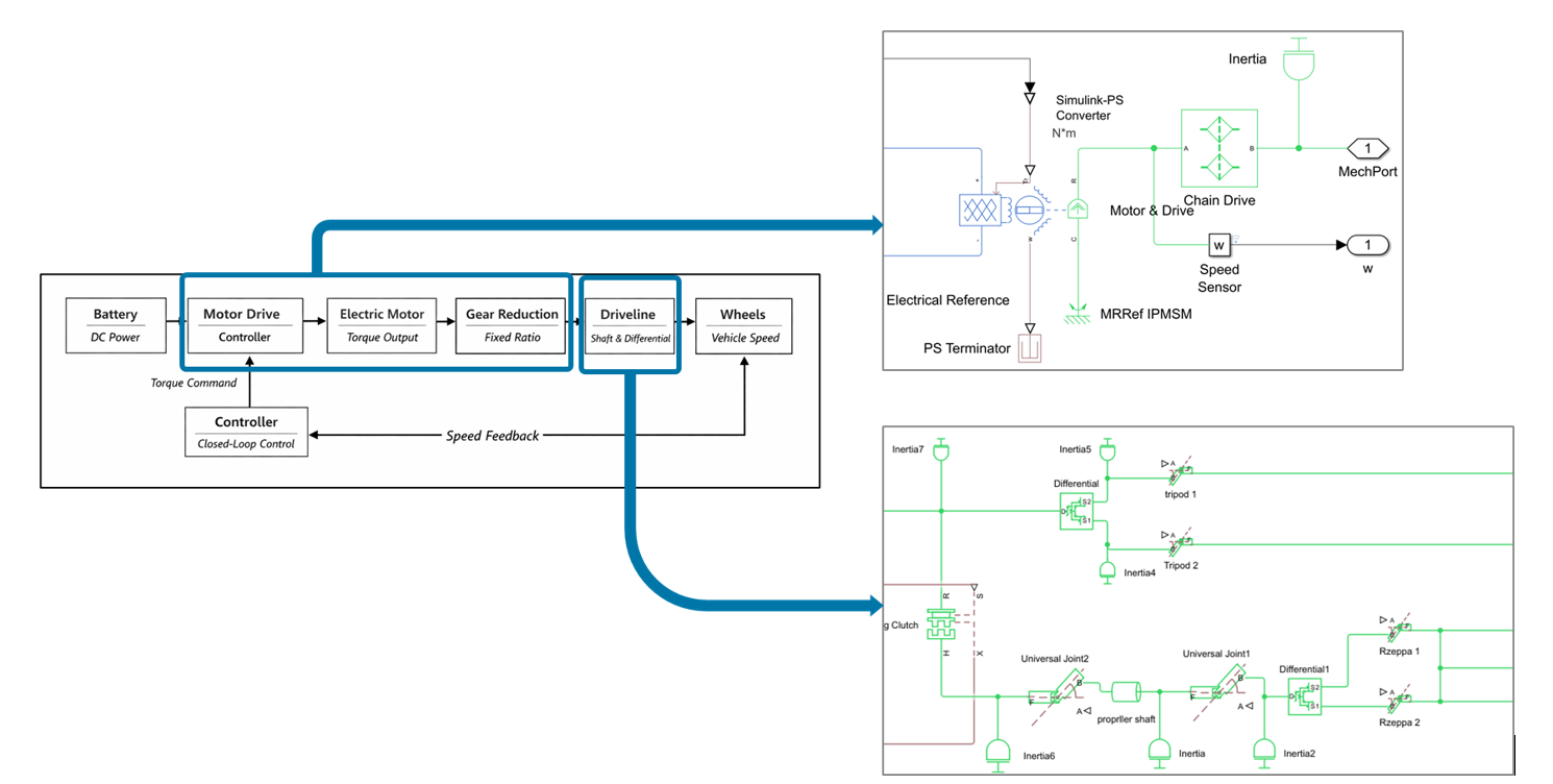
Figure 3: Powertrain model
Simulation Scenarios & Results
The model was tested using a drive cycle with acceleration, cruising, hill-climb, and braking segments to assess system response under varying loads and speeds. Scenarios included initial acceleration, steady cruising, and increased resistance. Analyses focused on vehicle speed vs. time, battery SOC, current, and power flow.
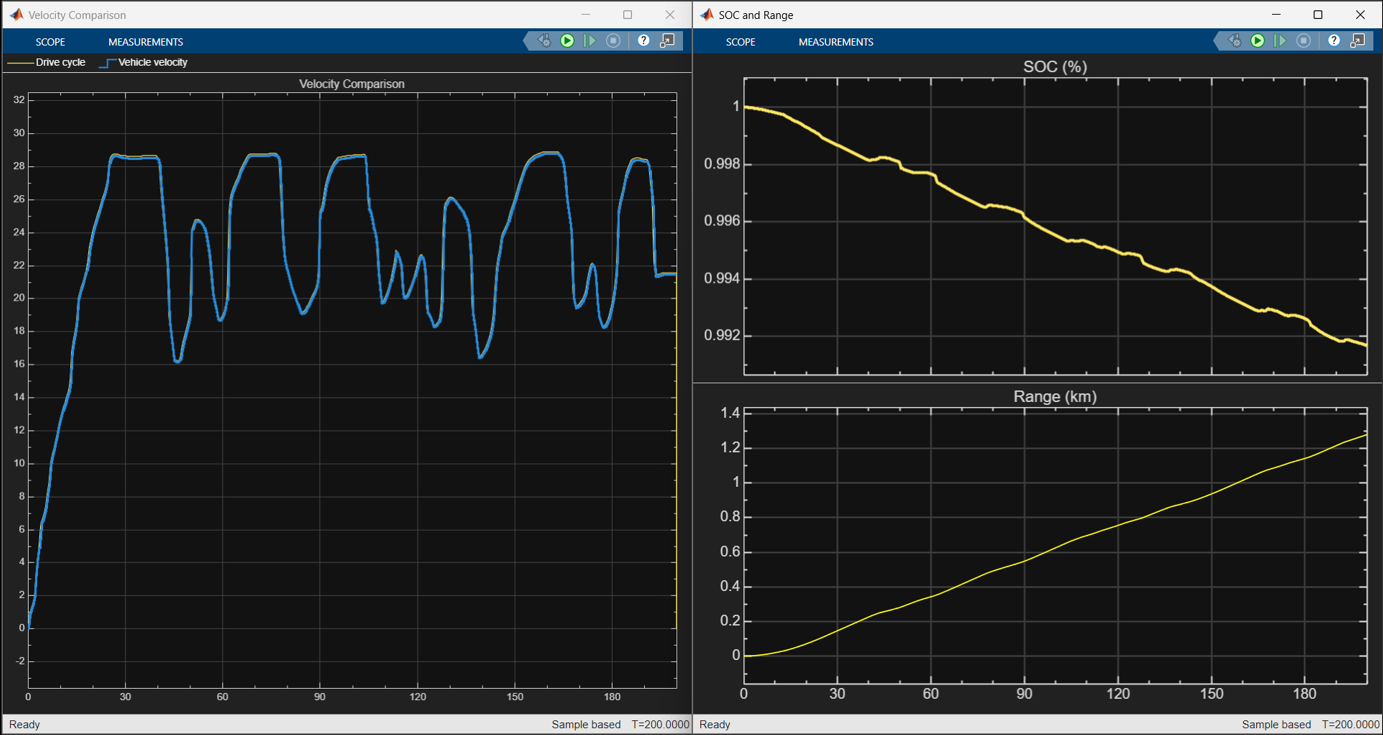
Figure 4: Simulation results
Simulated vehicle velocity closely followed the reference cycle, with only minor deviations in rapid transitions, demonstrating effective speed control. Battery SOC declined gradually, showing adequate capacity for the load. Peak current and power appeared during acceleration and resistance phases; cruising used less current, indicating efficient power use. Battery voltage stayed within safe limits, with expected minor dips during high-current events. Overall, the results confirmed stable operation and suitability for further analysis.
Key Design Insights & Learnings
The simulation revealed key design trade-offs: gearing impacts both top speed and low-speed torque; battery resistance and state-of-charge affect voltage and motor torque, so realistic modeling is crucial for accurate performance estimates; controller settings heavily influence tracking quality and current spikes. Validating assumptions proved essential—optimistic battery models and loose control gains led to misleading results, but iterative refinement improved accuracy and understanding. These insights show that even moderately detailed models can help student teams make more informed design choices than relying on heuristics or trial-and-error.
How Simulation Helped Us Think Like Engineers
________________________________________________________________________________________________________________________________________
“MATLAB and Simulink fostered a systems-thinking approach to powertrain design, where the battery, motor, controller, and driveline were treated as interconnected subsystems influencing overall vehicle performance. This approach helped us structure our models into well-defined subsystems with clear interfaces, validate model behavior against expected trends and reference drive cycles, and iteratively refine key design parameters such as battery capacity, gear ratio choices, and control gains based on simulation evidence rather than assumptions.”
________________________________________________________________________________________________________________________________________
What’s Next for the Team
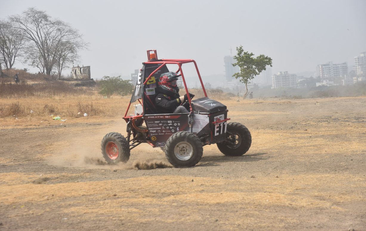
Our eBAJA vehicle on track
We aim to test more drive cycles, including endurance and high-speed scenarios, while improving loss and thermal modeling for better efficiency analysis. Matching simulation results with real vehicle data is a priority, so we’re refining assumptions to minimize discrepancies. We’re incorporating Kalman-filter-based estimators, advanced controllers, and additional input signals to enhance SOC and range predictions. Precise PMSM motor modeling and HPPC battery tests will help align simulated and physical performance. This foundation will enable future team members to explore new powertrain layouts, control strategies, and battery options through ongoing simulation-based development.
- 범주:
- Automotive


댓글
댓글을 남기려면 링크 를 클릭하여 MathWorks 계정에 로그인하거나 계정을 새로 만드십시오.