
Bringing DB-15 to Life with Model-Based Design
For this week’s blog post, we invited the DuBois Area Robotics team to share their journey and how they used MATLAB and Simulink for the 2025 BEST Robotics Championship. MathWorks is immensely proud of their achievements, and we hope you also find their insights useful! With that, I’ll hand it over to them.
Who We Are: DuBois Area Robotics
We are DuBois Area Robotics, a public high school robotics club based in western-central Pennsylvania. We have been competing in BEST Robotics since 2011 and VEX Robotics since 2019.
For BEST Robotics, we often include a few students from neighboring districts. One of the aspects of BEST that keeps us returning is its company-style structure, which requires us to integrate marketing, engineering, and design into a unified team effort. We also enjoy the challenge of building a competitive robot using only common materials that can be found in a typical hardware store.
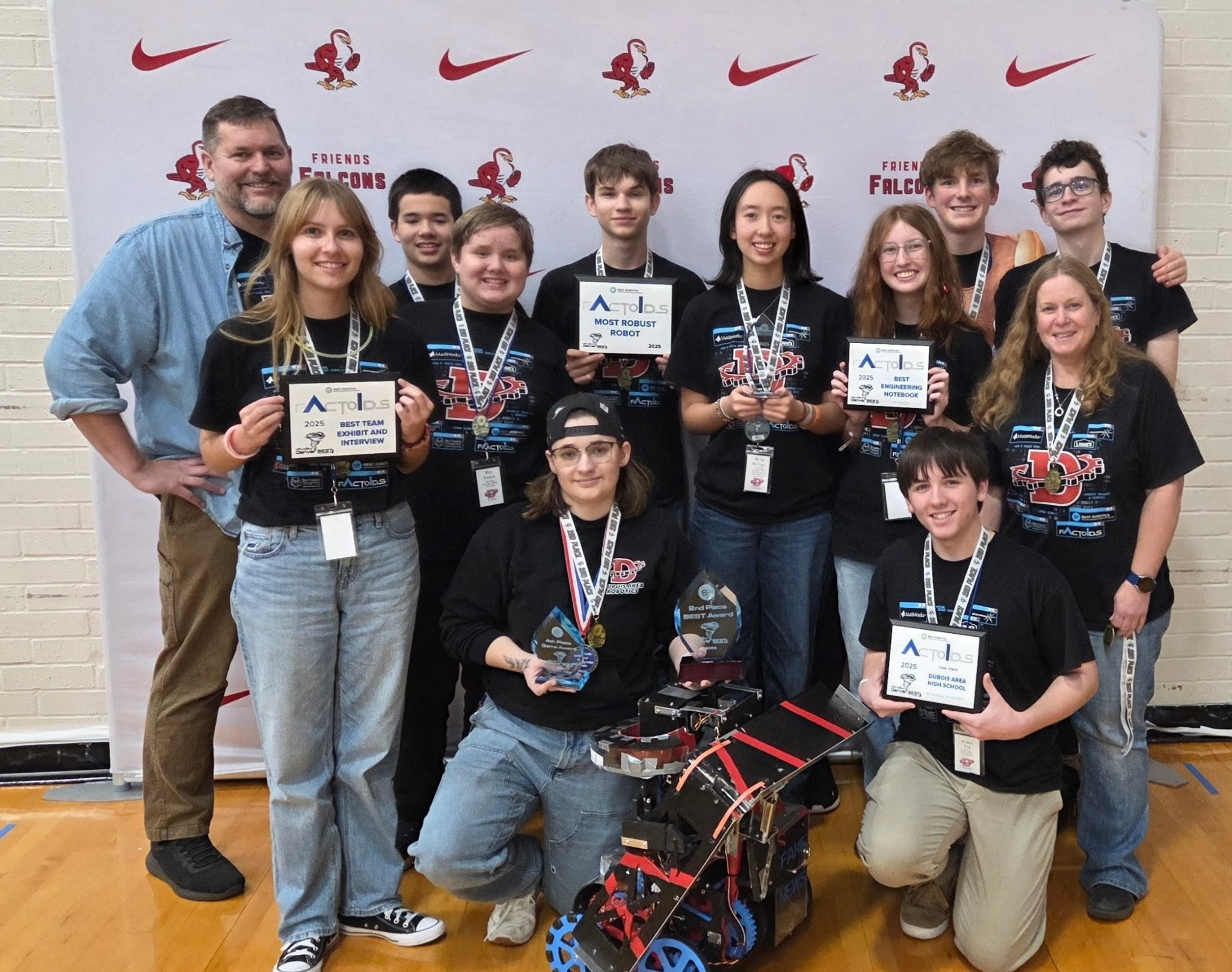
- Kneeling (L to R): Aubree Evans (CEO, Lead Driver), Aiden Via (Marketing Head)
- Standing (L to R, both rows): Ken Evans (coach), Marissa Gilga (Lead Exhibit), Mason Keller, Nic Evans, Derrick Weber (Lead Builder), Bela Keller (Lead Programmer), Peyton Walker (Lead Notebook), Paul McCloskey, Jen Keith (coach), Jack Stringer
- Not Pictured: Molly Sensor, Nolen Murray
Our Robot: [DB-15]
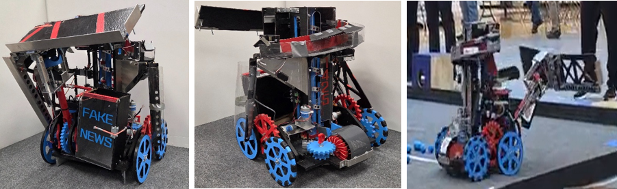
This year’s game, Factoids, was built around the concept of training an AI system. The major tasks were to connect a neural network and then train it with valid information, “true factoids”. Towards this end, we designed DB-15 to quickly connect the network and passively collect a large amount of factoids, autonomously sorting the true and false factoids.
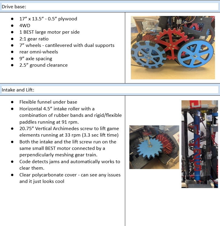
DB-15 measures 23” × 23.5” × 23.75” and weighs 24.00 lbs, and is built around five main subsystems that operate under both autonomous and driver control. Its wide wheelbase and large wheels were chosen to improve stability when climbing the ramp and navigating the field.
Factoid Collection & Transport
- The robot collects factoids through an intake on the back.
- Simply driving over factoids funnels them into the intake and then to the Archimedes screw in the center of the robot.
- The Archimedes screw transports both true and false factoids up into the sorting mechanism.
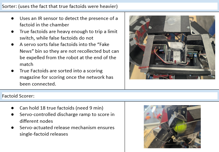
Sorting Mechanism
- An infrared sensor and a limit switch are used to differentiate between the factoids.
- The IR sensor first detects if there is a factoid in the sorting system.
- The limit switch acts as a pressure plate (the true factoids are heavier and will trigger the switch).
- True factoids are stored in a magazine until the driver is ready to score.
- False factoids are dropped into a storage box (“fake news” box) to prevent recollecting factoids that have already been sorted.
- At the end of the match, the arm can open the fake news box.
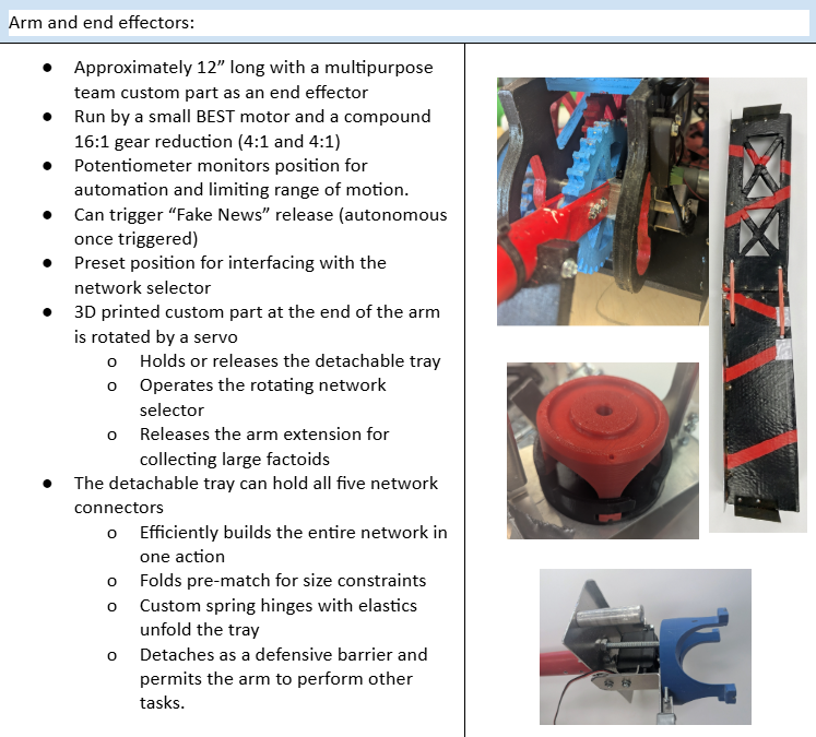
Arm & Scoring System
- The arm was geared for torque to control a heavy tray that can carry all five neural network tiles at once.
- The tray is hinged in the middle so it can fold to remain size compliant.
- The tray is connected to the arm using 3D-printed team custom parts that serve as a latch, end effector, and release trigger for an arm extension.
- Two neodymium magnets on the underside of the arm allow passive collection of true “Wall Street” factoids while actively retrieving a “Library of Content” factoid.
Our Design Process
We began by breaking down the game rules and fully understanding the scoring system. From there, we evaluated the difficulty of each task to develop a realistic strategy, focusing on areas where technical and programming solutions could provide an advantage. Once our strategy was defined, we created a list of core robot systems and their required functions and attributes.
Normally, we divide systems among small groups for parallel brainstorming, but due to our smaller team size, the entire design team worked through each system sequentially. Individual members then took ownership of specific ideas. Competing designs were evaluated collaboratively and integrated into the final robot design. Throughout the process, we consistently looked for opportunities where software could improve or simplify mechanical solutions.
We chose to use Simulink for several reasons:
- Simulation was valuable given our 8-week build season, where most of our time is spent constructing the robot and there is limited time for on-robot testing.
- It allowed us to develop and test control logic before hardware assembly, reducing the need for extensive debugging later.
- We could simulate controller inputs and observe system behavior, giving us feedback on signal flow and control response.
- The block-based environment made it more intuitive for modeling control systems and state logic than traditional text-based programming.
- Many of the systems on our robot are natural matches for Stateflow charts, and when they are not, we still have the option of using custom functions for text coding or manipulating them with other Simulink blocks.
Our team has been using Simulink since 2016 and prioritizes training at least one new member each year to support knowledge transfer. However, each season remains a learning experience, as most new members have limited prior exposure. While online courses and webinars are available, one of our coaches is pretty good with Simulink, and if we forget something, he can help with the basics or suggest an alternative approach.We also do a lot of online searches and look over Simulink videos from other years to learn about other approaches.
Last year, we were fortunate to have a former lead programmer mentor the team. Our current lead programmer is a junior with one year remaining, and we are actively training a younger member to take over in the future. He began in 6th grade, and Simulink’s visual programming environment made it significantly easier for him to learn core concepts early on.
Our Code Implementation
This year, we faced an additional challenge as BEST transitioned from the VEX Cortex to the VEX V5 control system. It was a late change, and we had to transition from the existing Simulink VEX Cortex support to the VEX V5 support package in Simulink, which required some adaptation. The main issue was the new motor controller (MC55) and missing input ports on the controller block (for simulation). As recommended, we used the V5 Smart Motor Write block to control the MC55, and after some testing, we were able to achieve consistent and expected motor behavior.
The V5 remote control blocks also did not initially support simulation inputs in our workflow. To enable full system simulation, we temporarily integrated Cortex-based blocks during early testing. While this added an extra step, it pushed us to explore Simulink’s signal routing tools more deeply. We discovered the variant source block, which was exactly what we needed. We had already been using signal buses to route some control signals, but the variant source block would solve our problem if we put all control signals into the same bus. From there, we addressed all signal routing and also used a bus for output signals. This made our code more manageable and even made adding new systems easier.
Our drivetrain has become standardized for our team. We typically use a tank-drive configuration with a speed cut controlled by a button latch. We also implement deadbands and a custom MATLAB function to improve low-speed precision by mapping joystick inputs to motor outputs using a non-linear function. This also compensates for signal loss introduced by the deadband block while preserving full output when needed.
Every other system on our robot is controlled using Stateflow charts. We define operating modes that the motors and servos need (such as on, off, forward, reverse), then create states and transitions accordingly. Visually seeing each state activate (or not) during simulation is a great troubleshooting tool. We try to locate tunable parameters outside of Stateflow charts as inputs to make them easier to understand and adjust. Our outputs are usually just control signals. If there are other values that need to be passed to other parts of the code, we tend to write them to memory.
There were a few design issues this year that were either solved or improved through our code. While we developed a low-tech factoid sorter, we found more consistent results with our sensor-based system. Instead of using physical limit switches on the arm, we added a potentiometer and used it to both limit motion and move to predetermined locations. We had also considered using it for PID control, but the arm performed well without it.
One problem inherent to our intake and Archimedes’ screw system was occasional jamming. While we addressed this mechanically, it wasn’t enough. Drivers could reverse the intake manually, but this took focus away from other tasks and reduced the advantage of passive collection. In previous years, addressing this in code would have been difficult, as the older control system provided no motor feedback, and the MC55 motor controllers do not either. Fortunately, we found and used advanced smart motor read/write blocks in Simulink and added them to our V5 library. They allowed us to monitor current drawn from the V5 brain by the MC55s. Using Simulink’s monitor and tune, we found the threshold that was crossed whenever the motor stalled. With this, the robot could detect jams in real time and automatically clear them without driver input.
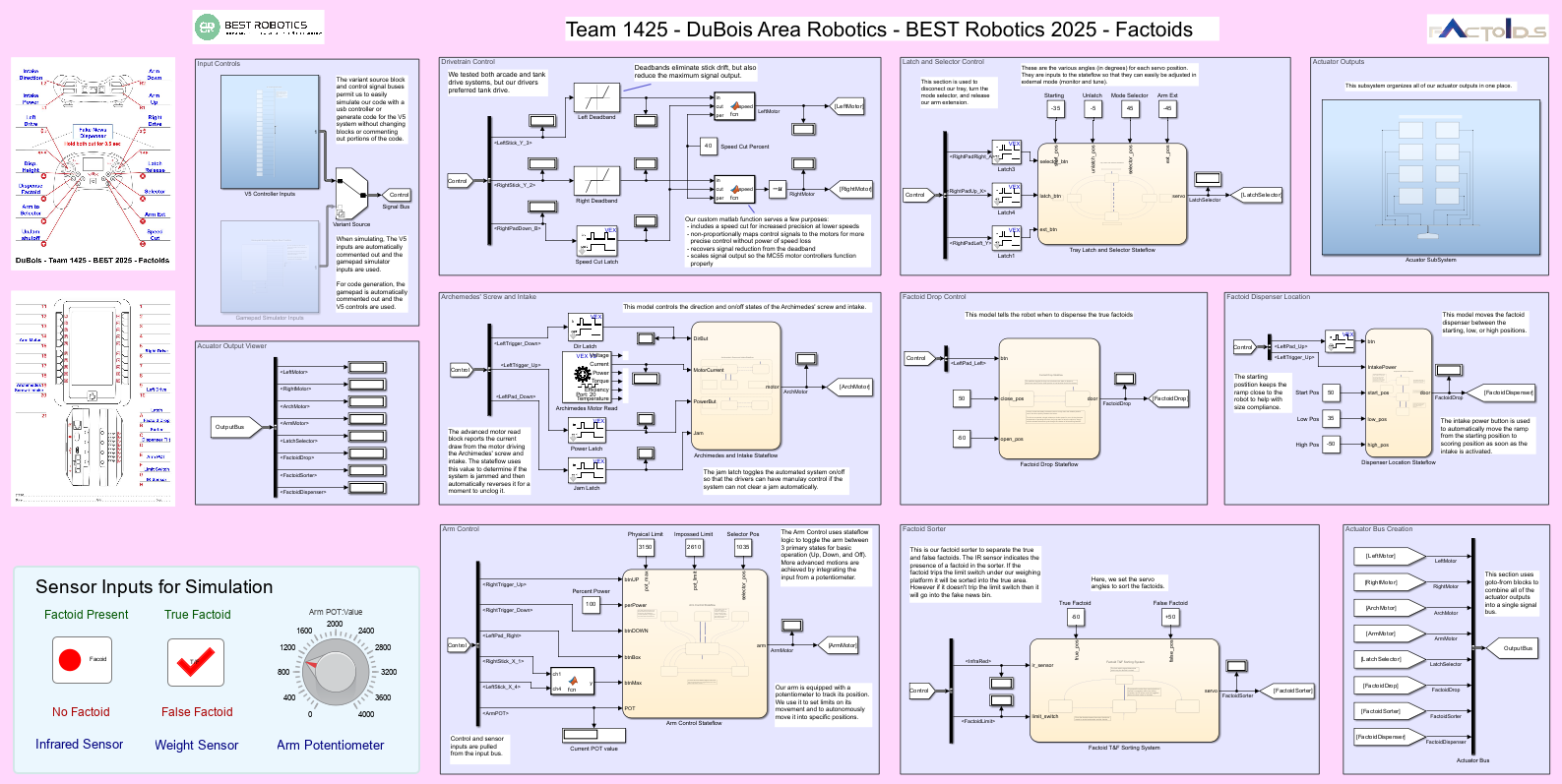
Code structure overview
We included a controller map and port diagram for reference. We also experimented with dashboard displays once we found the solution to them not working with larger Windows displays.
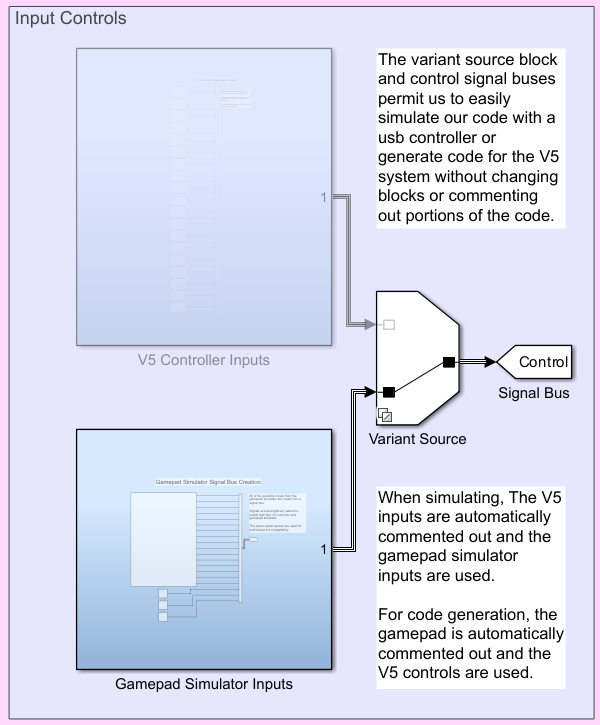
Variant source and subsystem architecture showing our control and sensor inputs, enabling seamless simulation and hardware deployment.
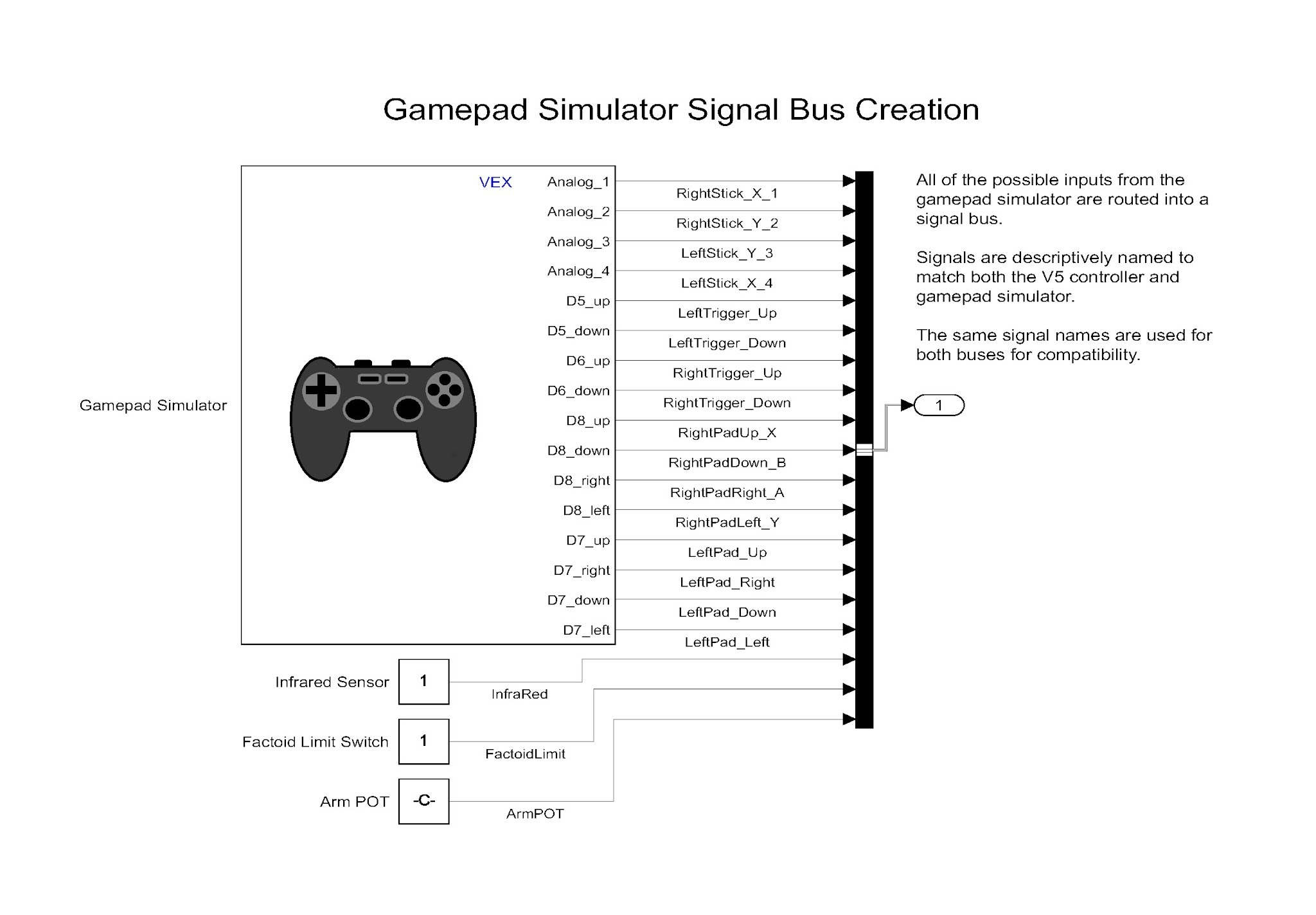
This subsystem combines the outputs from the gamepad simulator and our simulated sensor values (linked to the dashboard controls) into a single bus. We descriptively named each channel to make using the bus more intuitive. To avoid errors, we used the same signal names as our V5 control signal bus.
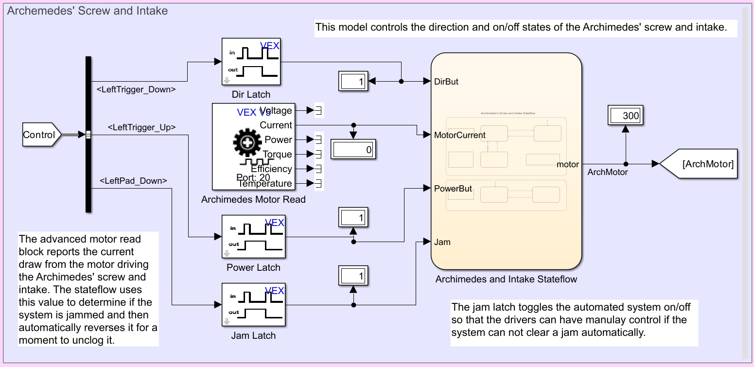
Here you can see the advanced smart motor read block. Only the first 2 values are actually output when using the MC55. Our signals are pulled from the control bus. This really cleaned up our code and process.
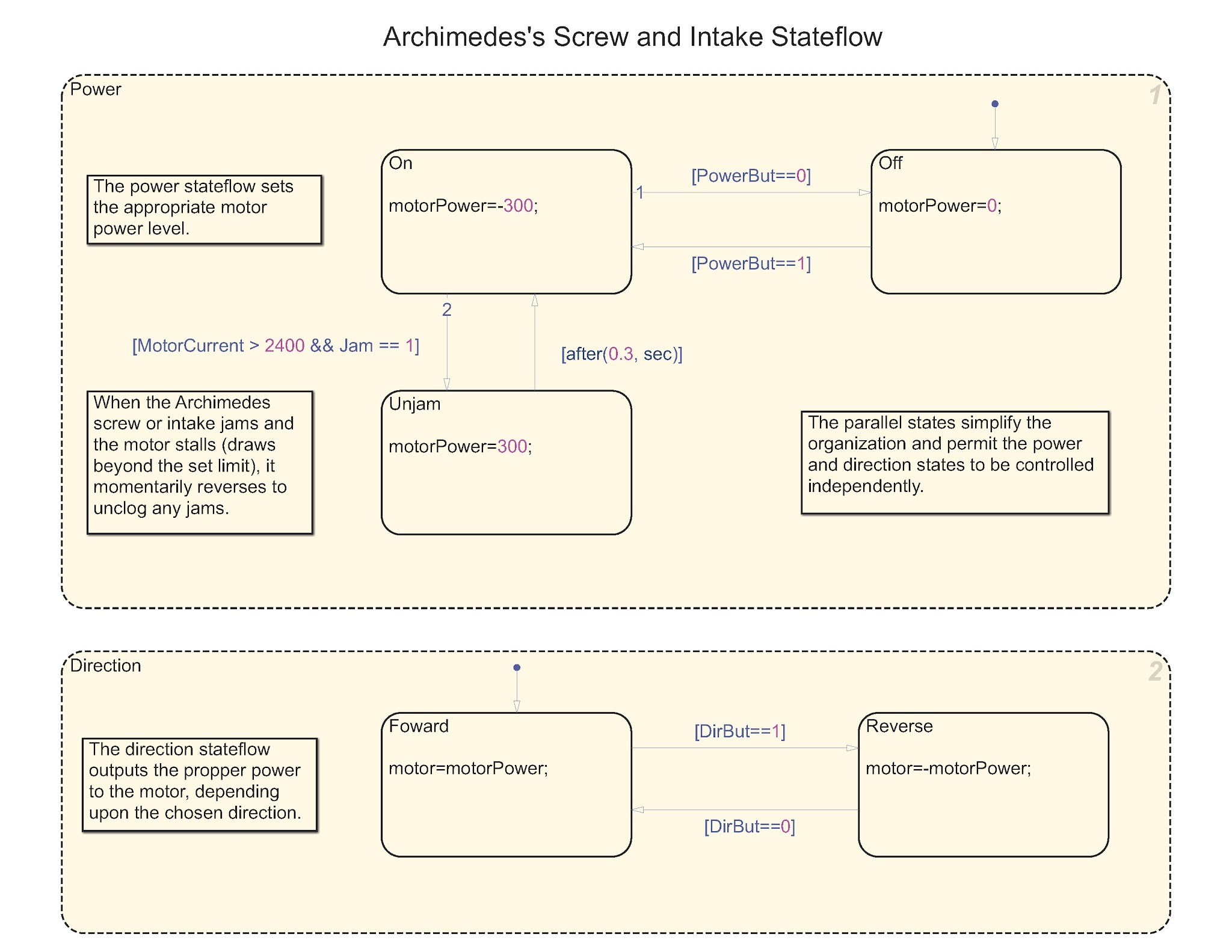
This is the Stateflow for the intake and Archimedes’ screw. To constantly monitor the system for jamming, we used a parallel Stateflow structure. (Parallel structure essentially allows multitasking.)
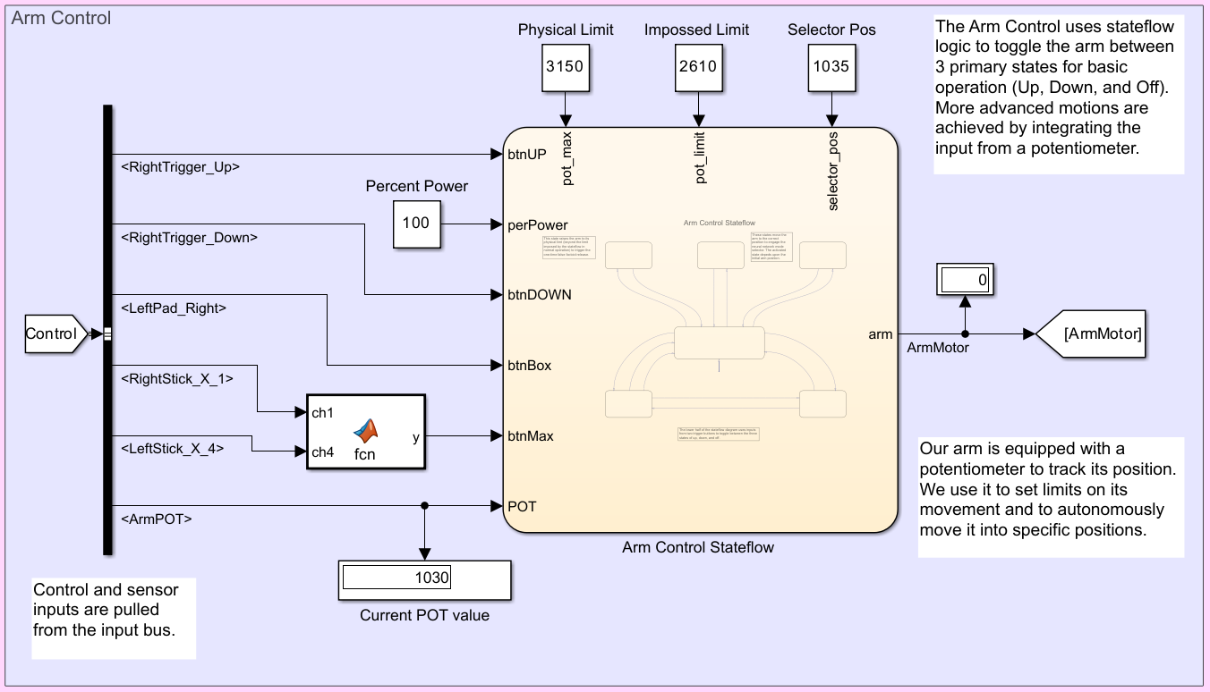
The arm performed numerous tasks, both autonomously and with driver input. Thus, it required quite a few inputs and parameters. The custom function only sends a true value after a very specific combination of joystick movements is held for a predetermined time.
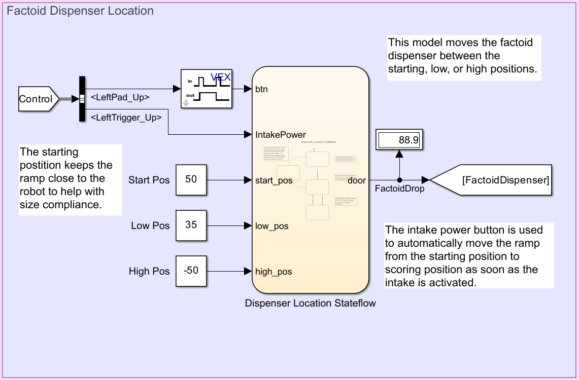
This section controls the position of our factoid dispenser ramp. Adjustable values are clearly noted outside of the Stateflow where they can be adjusted. The Stateflow chart automatically moves the ramp from the starting position to the lower scoring position as soon as the intake is started. This prevents driver error as the two positions are hard to discern from across the field
Here is our submission to the Simulink Design Award:
Highlights from the Denver BEST Regional Championship
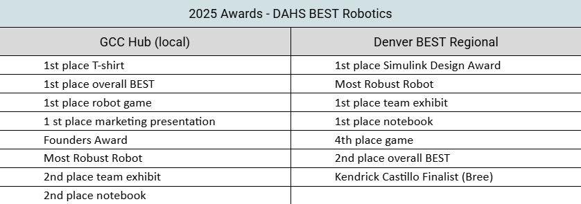
DuBois Area High School competes at the local Grove City Competition each year. This event qualifies teams for the Regional Championship. We did quite well this year, winning a number of awards and securing our place at regionals.
Our regional competition is the Denver BEST Regional, which was held in Wichita, Kansas, this year. There, we faced the top teams from seven other regionals. Our team’s work was recognized with several awards, including 2nd place in the Overall BEST award and winning the Simulink Design Award. We are especially proud of these achievements, as we are one of the few public high schools competing at both our local and regional events. Additionally, our 2025 team was our smallest ever, and each member worked hard to help overcome that challenge.


コメント
コメントを残すには、ここ をクリックして MathWorks アカウントにサインインするか新しい MathWorks アカウントを作成します。