
Simulink-Based CAN Control and Validation on STM32F4 for a Dual-Motor EV Platform
In today’s blog, we are joined by Team I.C.C. from Inha University, South Korea. They share how they used MATLAB and Simulink to develop and validate a CAN-based embedded motor control workflow for their dual-motor EV platform. Over to you…
Introduction
I.C.C. (Inha Car & Computer) is a student club at Inha University (South Korea) dedicated to automotive research, design, and hands-on electric race car production. Through activities such as developing electric racing vehicles, building embedded control systems, and preparing for engineering competitions, I.C.C. provides students with opportunities to gain practical experience in electric racing car development, teamwork, and problem-solving within the field of future mobility. In this project, the team focused on building and validating a Simulink-based CAN control workflow on STM32F4 for a dual-motor EV platform. Rather than presenting the work only as a dual-motor hardware project, this blog highlights how model-based design made CAN implementation, deployment, and real-time validation much easier to manage in practice.
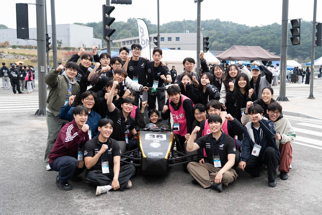
Figure 1. I.C.C. club members at a racing competition with the electric racing car (Inha University, South Korea)
Motivation
For our EV racing car, we needed more than a basic motor test. The real challenge was to establish a practical workflow for CAN-based control and validation on STM32F4 so that motor commands could be generated from live input, transmitted reliably, and checked against real hardware feedback during operation. While this workflow was developed for a rear-driven dual-motor platform and can later support torque vectoring, the immediate goal of the project was to make CAN-based control easier to implement, deploy, and verify.
To make that possible, the workflow had to go beyond fixed CAN message tests and support a complete embedded control loop with:
- variable driver input,
- independent motor command generation,
- reliable CAN communication, and
- real-time feedback monitoring.
In the early hardware test stage, motor operation was checked mainly with predefined CAN commands in STM32CubeIDE before the pedal signal was connected through ADC. That approach was useful for basic validation, but it made it harder to iterate on continuously changing commands, integrate real input processing, and monitor the full control path in a structured way. To address this, we developed an embedded Simulink-based workflow on STM32F4 that combined throttle input processing, CAN-based command transmission, code generation and deployment, and feedback monitoring in one model. This shifted the project from isolated CAN testing toward a repeatable workflow for embedded control and validation, while still leaving room to expand into dual-motor coordination and future torque-vectoring logic.
As a result, we established a practical CAN-based embedded workflow that could read real throttle input, transmit motor commands, and monitor feedback in real time on STM32F4. The validated workflow was then extended to a dual-motor structure, providing a solid foundation for future vehicle-control features such as torque vectoring.
Breaking down the problem
To build a practical CAN-based motor control workflow on a rear-driven dual-motor EV platform, the problem had to be approached as a control, communication, and validation challenge rather than as a simple motor test. The embedded system needed to convert driver input into commands, transmit them reliably over CAN, receive meaningful feedback, and organize the structure in a way that could later scale to independent left-right control.
1. Converting Driver Input into Torque Commands
The first requirement was an input-to-command path that could convert variable driver input into torque commands suitable for vehicle control. Fixed test commands were not enough, because torque vectoring depends on continuously changing motor commands based on throttle input and, eventually, vehicle-state-based control logic.
2. Establishing Reliable CAN Communication
The second requirement was a reliable CAN communication structure for both transmission and reception. On the transmit side, the controller needed to send properly formatted torque commands to each motor controller. On the receive side, it needed to collect feedback signals such as battery voltage, torque, RPM, and motor voltage so that each motor’s response could be monitored and validated during operation.
3. Building a Scalable Dual-Motor Control Structure
The third requirement was support for independent dual-motor control as a foundation for future torque-vectoring algorithms. This meant extending the validated single-motor structure into a scalable architecture in which the left and right motor paths could be configured, tested, and monitored separately. The goal was not simply to make two motors rotate, but to establish a dual-motor embedded control platform that could later support higher-level vehicle dynamics control.
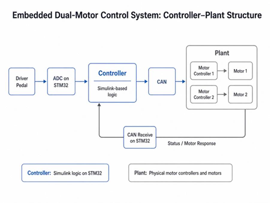
Figure 2. The overall structure of the dual-motor system
How did we implement it?
To implement this workflow, we developed the control structure in Simulink and deployed it on STM32F4 using the STM32 Microcontroller Blockset. The main objective was to bring CAN communication, throttle input processing, code generation, deployment, and feedback monitoring into a single model-based workflow that could be refined quickly during hardware testing. STM32F4 was a good fit because it offers built-in CAN interfaces, ADC inputs, and enough real-time performance for embedded motor control. We organized the model into functional subsystems for input processing, command generation, CAN transmission, CAN reception, and monitoring, which made the workflow easier to understand, debug, and extend from a single-motor test setup to a dual-motor platform.
We started by emulating pedal behavior in Simulink with a slider block, then later connected that same signal path to the actual ADC throttle input. This made it easy to move from simple bench testing to a more realistic dual-motor workflow driven by real input. On the transmit side, the throttle signal was translated into a motor command and packaged to match the motor controller protocol. Because the command changed continuously with the input, we were able to test dynamic motor actuation rather than relying only on fixed commands. By separating the CAN paths for each controller, we also created a structure that could support independent left and right motor control in future vehicle tests.
On the receive side, the focus was on checking whether the motor controllers were responding as expected during operation. Since the controllers returned several different status groups, we used a MATLAB Function block to parse the incoming CAN data more efficiently. This allowed us to monitor key feedback signals such as battery voltage, torque, RPM, and motor voltage in real time. As a result, we gained a much clearer picture of how each motor was behaving and could validate the dual-motor setup in a more systematic way.
Debugging was also much more manageable with CAN STATUS information, Monitor & Tune, and real-time monitoring in place. Instead of depending only on serial print messages, we could inspect internal signals directly and quickly tell whether an issue came from the model itself or from hardware conditions such as wiring and connections. We could also visualize the monitored signals as plots and export them as CSV files for later analysis, which made it much easier to review test results and compare behavior across hardware runs.
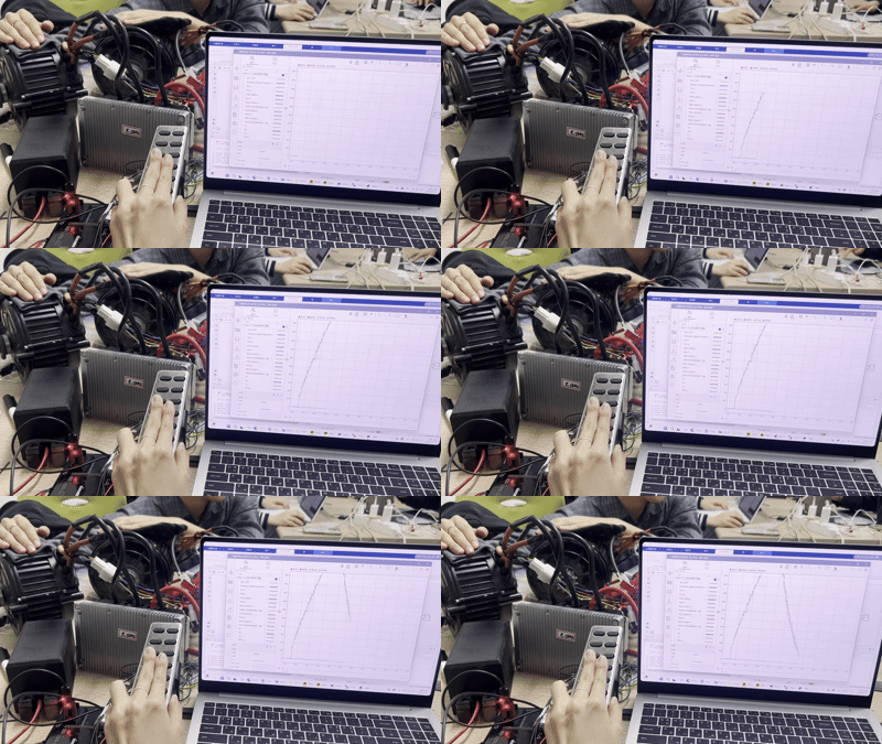
Figure 3. Real-Time hardware test with STM32F4, CAN communication, and dual motors with Simulink
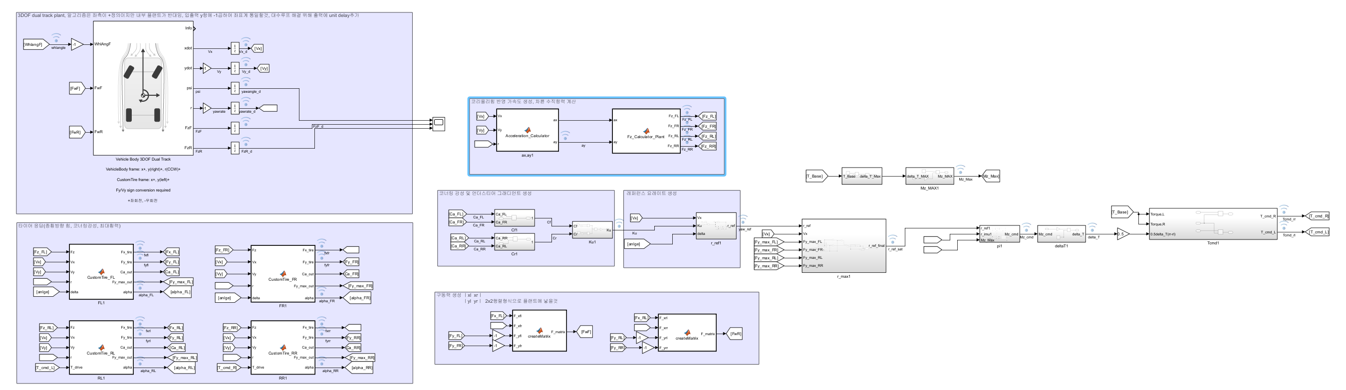
Figure 4. A Simulink-based torque-vectoring control architecture built on top of the validated dual-motor workflow.
Results
The biggest outcome of this project was that we established a Simulink-based CAN control and validation workflow that could be deployed directly to the real vehicle platform through STM32F4. By connecting the real ADC throttle input and generating CAN-based motor commands from the model, we showed that driver input could flow through the complete embedded path—from pedal signal, to controller logic, to CAN transmission, to actual motor response and feedback validation on hardware. This made the project more than a bench-level motor test; it became a practical demonstration of model-based embedded control on a real EV platform.
Just as importantly, the Simulink-based workflow made implementation, deployment, and debugging much easier to manage than a conventional low-level approach centered on predefined CAN commands in STM32CubeIDE. Instead of repeatedly modifying C code for every small change, we could adjust signal scaling, data types, CAN formatting, and sample times directly in the model and then regenerate and redeploy the code more efficiently. Monitor & Tune, CAN STATUS information, and real-time monitoring also made validation much more systematic, because we could inspect internal signals directly and identify whether issues came from the model logic or from hardware conditions such as wiring and connections. The modular structure further made it easier to expand the validated workflow from a basic test case into a dual-motor architecture, giving us a scalable starting point for future vehicle functions such as torque vectoring.
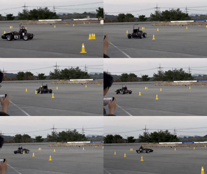
Figure 5. The EV racing car is in test with torque vectoring implemented
- 범주:
- Automotive


댓글
댓글을 남기려면 링크 를 클릭하여 MathWorks 계정에 로그인하거나 계정을 새로 만드십시오.