Steve on Image Processing

May 11th, 2007

Connected component labeling - Part 5

OK, I've learned an important lesson about this blog: I really shouldn't start up two topics series at the same time. It's too hard to find the time to compose posts on both topics each week, and so the frequency of my posts drops off.

Anyway, let's get into the third algorithm for labeling connected components in a binary image. It involves two passes over the image, with an in-between step called equivalence class resolution. I first learned about this idea from Haralick and Shapiro, Computer and Robot Vision, vol. I, Addison-Wesley, 1992.

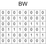
The first pass assigns temporary labels to each foreground pixel. Here's a graphical illustration of that procedure, using this small sample image:

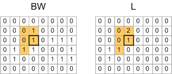
Now scan the image, processing one pixel at a time. Because of the way MATLAB stores matrix elements in memory, we'll scan along columns. When the scan encounters a foreground pixel, look at that pixel's neighbors that have already been encountered in the scan. Here's the first foregound pixel encountered, shown with its already-scanned neighbors highlighted in color:

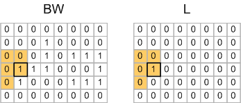
For the pixel shown above, none of the highlighted neighbors have been assigned a temporary label yet, so a new label value (1) is assigned to the corresponding pixel in the output.

Here's the second foregound pixel encountered:

Note that one of this pixel's neighbors has already received a label (1), so this pixel is also assigned a temporary label of 1 in the output image.

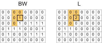
When the scan gets to row 2, column 4 pixel, none of that pixel's scanned neighbors have been labeled, so that pixel gets assigned a new temporary label of 2.

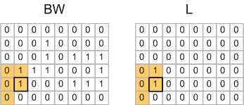
The very next pixel, on row 3, column 4, is where things start to get more interesting:

One of this pixel's scanned neighbors has already been assigned a label of 1, but another of the neighbors has been assigned a label of 2. So the algorithm picks one of the labels arbitrarily, and then records the fact that temporary label 1 and temporary label 2 actually refer to the same object.

This situation happens again on row 4, column 8:

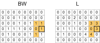
So the pair of labels 3 and 4 is an equivalence and goes into the equivalence table.

When the first pass is done, you have this matrix of labels:

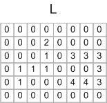
And you have an equivalence table containing these pairs:

 1 <--> 2
 3 <--> 4

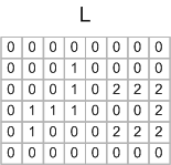
Equivalence class resolution is the process of determining which subsets of the temporary labels really refer to the same object. You can do that in MATLAB using the technique I showed previously that was based adjacency matrix and dmperm. From this you would compute that temporary labels 1 and 2 map to final label 1, and temporary labels 3 and 4 map to final label 2. Then you make a second pass over the output matrix to relabel the pixels according to this mapping:

The Image Processing Toolbox function bwlabeln uses a variation of this technique, where the equivalence class resolution is actually performed during the first pass, using an algorithm called union find. I'll explain that next time.


Get the MATLAB code

Published with MATLAB® 7.4

30 Responses to “Connected component labeling - Part 5”

  1. hamed kowsari replied on :

    very nice
    tanks

  2. vanessa replied on :

    Hi, please can you give me the Connected component labeling algorithime, in preference written in matlab, i extremely need it. thank’s

  3. Steve Eddins replied on :

    Vanessa—Use the function bwlabel or bwlabeln in the Image Processing Toolbox.

  4. vanessa replied on :

    i have used these instructions and more, but it don’t give the result i wish, because the indexed image that i have is composed with labels {0,1,2,3,…} not {O,1} only. i have tried to transform it to an {0,1} image, but I did’nt succeed.

  5. Steve Eddins replied on :

    Vanessa—Try im2bw to convert your indexed image to binary.

  6. vanessa replied on :

    I have already used it, but with the intial image which is color one, in this case that instruction im2bw merge the regions which have a near color, and that’s wrong. so i have give a label to each color, and i got an indexed image with these labels {0,1,2,..}. now i will try to apply im2bw to my indexed image, i’ll tell you. thank’s

  7. vanessa replied on :

    this have given a result indexed with {0} only because the indexed image is taken as an intensity one in matlab, what can i do?

  8. Steve Eddins replied on :

    Vanessa—I think it might help you to review the introductory information in the Image Processing Toolbox Users Guide about the different image types and how to convert between them.

  9. vanessa replied on :

    I have already learnt this guide, and i know all the instructions given, i have tried all of them and also combined them, but in vain. my problem is to convert a classified indexed image to a labeled indexed image, for example i’ve to give to two regions which belong to the same classe and are not connected two diffrents labels , using -why not- Connected Component Labeling. thank’s for your help.

  10. vanessa replied on :

    hi, your help gave me a new idea, 1000 thanks. i’ll communicate u the result.

  11. vanessa replied on :

    i’ve solved my problem. thank’s for your help.

  12. Juliana replied on :

    Hi, please can you give me the Connected component labeling algorithim but my image is grayscale and not in bw, in preference written in matlab.
    I have read yours informations, and I think my problem is very same with the previus.
    Thanks

  13. Steve replied on :

    Juliana—If you can define very clearly what you mean by “connected components” in a grayscale image, I might be able to make a suggestion. I do not send people custom code, however.

  14. peter replied on :

    Hi Steve, is it possible to label/find connected components in a matrix composed of integer from 0 to 10 (not a binary matrix). I want to find continuous areas of the matrix that have the value 1, 2, etc. I could create a loop (for i=1:10) and replace every value in the matrix other than i by zero, but is there a easier solution?
    I really enjoyed your series on connected component labeling
    Thanks

  15. Steve replied on :

    Peter—Connected-component algorithms can be adapted to compute what I believe is called “flat-zones labeling.” It would take some work, though, to program such a thing. Possibly the simplest implementation in MATLAB would be along the lines of what you suggest: Label f==1, then label f==2, etc.

  16. shailesh replied on :

    hi steve,

    can you discuss gray scale connected component labelling algorithm?

    thanks

  17. Steve replied on :

    Shailesh—I’ll put it on my list of possible blog topics. Thanks for the suggestion.

  18. Edgar replied on :

    Hi Steve,

    I am trying to find some blob detection algorithm/function already implemented in matlab. Is there something as such? I tried segmenting the image and then filling it and have some sort of bw image. Then I use bwlabel to find ‘blobs’. However, it is not as good as I would like and I am wondering whether exists something already to do this.

    Thanks a lot.

  19. Steve replied on :

    Edgar—The function bwlabel computes the connected the components of your binary image. That’s a well-defined operation - it’s either being computed correctly or it isn’t. So can you elaborate on what you mean by saying the result is not “good”?

  20. Edgar replied on :

    Thanks Steve, in fact, I have done it using bwlabel but tweaking the parameters of the edge function a bit.

  21. Karthik replied on :

    Hi Steve, i have a problem in using dmperm function, as my adjacency pairs are not incremental. ie. example in below case i dont have label 4, as it forms a individual un-connected cluster.

    pairs = [ 2 3; 3 2; 1 2; 2 1; 5 6; 6 5];

    here i have 5 nodes in total (ie. 1,2,3,5,6)

    A = sparse(pairs(:,1), pairs(:,2), 1);
    A(1:5+1:end) = 1;

    [p, q, r, s] = dmperm(A);

    this does not give correct result. how to solve this problem?

  22. Steve replied on :

    Karthik—You didn’t check your A matrix. This line:

    A(1:5+1:end) = 1;
    

    doesn’t do what you thought it would.

    See this comment from Tim Davis about efficiently putting 1s on the diagonal of a sparse matrix.

  23. Nawal replied on :

    hi steve.
    How we can detect an overlaping between connected cmponent.
    can you help me.

    Thanks in advance
    Nawal

  24. Steve replied on :

    Nawal—You can’t have two connected components that are overlapping. “Overlapping” indicates that you really only have one connected component.

  25. Nawal replied on :

    Thank you Steve.

    Sorry, in my case there is an overlap between bounding box of connected component not in connected component it self. I read today in some research paper the follwing idea we can use convex hull of connected component. where if there are an overlaping between two convex hull there are an overlap between bounding box of component.

  26. Steve replied on :

    Nawal—You can the convex hull of each connected component via regionprops. Then you need a routine to determine if two polygons overlap. You don’t a routine that works for general polygons, because the convex hull polygons will be, well, convex. :-) You might try searching the MATLAB Central File Exchange in addition to Google.

  27. DP replied on :

    Hi Steve:
    i am happy to saw that your update on “Image visualization using transparency” to label the two connected objects as a single object.
    However, i am having a problem with seperating two overlap object to seperate. in binary image i am trying to seperate two/three overlap rectangular object to seperate them and calculate the centroids of each seperated object. could you please show me one example?

    Thank you.
    Sincerely,
    DP

  28. Steve replied on :

    DP—There are one or two Image Processing Toolbox product demos that might be helpful.

  29. Alvin replied on :

    Hi steve,
    I go thru’ the bwlabel and bwlabeln, but i don’t understand how to write the algorithm with referring its theory. Mind to put on a simple example for my reference?
    Million thanks to you, Steve.

    Rgds,
    Alvin

  30. Steve replied on :

    Alvin—I already wrote a lot about these algorithms in this series. Be sure to check out all the related posts. There’s also quite a lot of information about connected components labeling available in other online sources.

Leave a Reply

Wrap code fragments inside <pre> tags, like this:

<pre class="code">
a = magic(3);
sum(a)
</pre>

If you have a "<" character in your code, either follow it with a space or replace it with "&lt;" (including the semicolon).


Steve Eddins manages the Image & Geospatial development team at The MathWorks and coauthored Digital Image Processing Using MATLAB. He writes here about image processing concepts, algorithm implementations, and MATLAB.

  • Sana: hi steve, could you explain to me how i would be able to use the dir function, to do a loop through a directory...
  • Nishtha: Sir, I have preprocessed the image in following steps: [1] adaptive histogram equalization [2] thresholding...
  • Kristof: I also strongly support the idea. I have just recently bumped into the problem that im2single was not...
  • Steve: David—I’ m glad you found it useful!
  • David Lalejini: I found your example very useful for finding connected nodes in a large set of input pairs. I start...
  • tommy: Dear Steve, I have a question,please if you are kind to help me regarding the accumulator array dimensions of...
  • Steve: Abc—I don’t know how to distinguish the faces. You might try posting your question in the MATLAB...
  • Manju: well if we have a few ovals within each other like in a cell how do we measure the distance from the center...
  • Steve: Manju—What do you mean? How is each region defined?
  • Manju: if we have 2-3 regions within each other how do we measure the regions of each one?

These postings are the author's and don't necessarily represent the opinions of The MathWorks.