
Developing Adaptive cruise control using Fuzzy Logic
Joining us today is Jared Diethorn from the West Virginia University EcoCAR Team. Jared and His team took an interesting approach to Adaptive cruise control in the EcoCAR Mobility challenge by using Fuzzy Logic. In this blog he’ll walk you through their approach. Jared continues this work with his team in the EcoCAR Electric Vehicle Challenge. Take it away Jared!
Competition overview and team introduction
My name is Jared Diethorn, and I am a graduate research assistant currently studying for a PhD in mechanical engineering at West Virginia University (WVU). I have been with the team since Year 2 of the EcoCAR Mobility Challenge (EMC) where I obtained a master’s degree in mechanical engineering. The EMC challenged 11 teams in North America to convert a 2019 conventionally powered Chevrolet Blazer into a prototype hybrid. In additional to this concept, teams were challenged with constructing algorithms to bring the vehicle to an SAE level 2 autonomy. SAE level 2 is defined as partial autonomous driving with lessened driver responsibilities. For example, the vehicle may be capable of adaptive cruise control (ACC), however, the driver must remain alert at the wheel and must be prepared to take control of the vehicle’s acceleration and/or deceleration at any time.

The Connected and Automated Vehicles (CAVs) team, led by Zachary Flanigan and myself, achieved first place in the CAV Perception and ACC Drive Quality event at the Year 4 competition in Yuma, Arizona. The work involved designing ACC and perception algorithms to properly track and follow behind a lead vehicle over the duration of the event. These algorithms were designed in a centralized architecture and ran as executables on an Intel IOT Tank. In the final year of the EMC, the team opted to design two ACC controllers in parallel with a friendly competition between students, with the winning group implementing their control strategy into the WVU EcoCAR Blazer at the Year 4 competition.
What is Adaptive Cruise Control?
Adaptive cruise control, often referred to as ACC, permits the driver to hand the demands of acceleration and deceleration of the vehicle over to various algorithms deployed in the vehicle. From a higher perspective, when no obstacles are detected, the vehicle will follow a predetermined driver set speed and function as a standard cruise controller. However, if a slower moving vehicle is detected within a prescribed distance of the ego vehicle, the controller may decide to lessen the ego vehicle speed to follow the lead vehicle accurately and safely at a speed equal to or less than the vehicle set by the driver.
When designing an ACC system, some may think of PID control, which is a common control scheme where an input error signal is driven to zero over some desired amount of time. When tracking a set speed, a less aggressive control may be desired to increase vehicle efficiency and/or fuel economy. Similarly, if tracking a lead vehicle, the controller may have requirements to drive the distance error between vehicles to zero over a much shorter period to always ensure driver safety.

Once designed, controllers must be tuned and in the case of PID controllers, many factors including the response time and mass of the vehicle must be factored in appropriately to achieve the desired control response. The result is an algorithm that works effectively but may take repeated attempts to design according to a set of requirements. If vehicle dynamics are changed during the implementation process, the PID controller may need to be re-tuned. However, fuzzy logic can be introduced to present a different approach to the idea of creating and tuning a controller to follow student designed requirements and metrics in a more simplistic manner.
Introduction to Fuzzy Logic
Fuzzy logic serves to bridge the gap in binary logic. While binary logic can take on values of true and false (1 and 0), fuzzy logic can represent values in the range from 0 to 1 [0 1]. It is normally employed to handle responsibilities of the concept of partial truths and can take on any value from completely false to completely true. A common example for understanding fuzzy logic is the idea of a change in water temperature. Binary logic may state that water is cold if below 70 °F and hot when above 70 °F. However, is this statement true? Can water be deemed hot or cold when the difference in temperature is less than a tenth of a percent and can people really feel the difference? Fuzzy logic introduces partial truths, which could say that if the water is between 68-72 °F, then the water is warm. Several examples for breaking the temperature down in terms of fuzzy levels are shown in the table below. Once the general layout is decided, the fuzzy values are broken down into membership functions (MF) that can take on triangular, trapezoidal, or even gaussian shapes. The MFs are the backbone that relate crisp (measured) values into fuzzy values and vice versa.

One of the benefits to fuzzy logic design is that it is based on human to machine interpretation, meaning that the person designing the system can set up the membership functions in an intuitive way to solve the engineering problems at hand. While some engineering expertise in the problem is helpful, it is not required when implementing fuzzy logic. The WVU EcoCAR team is comprised of students from different backgrounds in engineering, however, fuzzy logic is a very intuitive tool to use. Some students have a background in control systems design, while others have more experience with fundamentals and the theory behind certain design characteristics of systems. For these reasons, implementing fuzzy logic meant that students from different areas could grasp the design process quickly and apply more intuition to reduce the amount of time spent designing, modeling, and tuning the controller.
WVU Fuzzy Logic ACC Algorithm
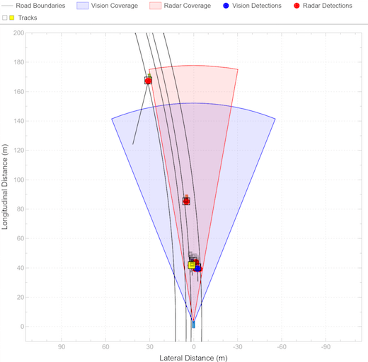
At the Year 4 final competition, the team opted to use fuzzy logic over the conventional control algorithms based on simulated and vehicle performance evaluations and to stand apart from other teams. For the controller to operate correctly, the team opted to use three inputs to one output fuzzy logic controller (FLC), also classified as a multi-input single-output (MISO) system. Inputs included the speed and distance error of the system as well as the relative speed with respect to a target vehicle in front of the Blazer. Once the crisp values are converted into fuzzy inputs, the inference rule matrix is used to determine the appropriate fuzzy output torque command to the system. In the output layer, the fuzzy output is converted to a crisp torque command that is sent to the engine and motor controllers respectively. The following figure highlights the controller architecture which was developed with the Fuzzy Logic Designer app provided in MATLAB by MathWorks.

Once the inputs and output on the system were agreed on, the resolution of each signal was considered due to the limited capability of running the algorithm in real-time in conjunction with the perception and sensor fusion algorithms. While gaussian MFs are computationally intensive, they also create smooth transitions when moving from one MF to the next, so gaussian MFs were implemented in all three inputs and the output of the controller.
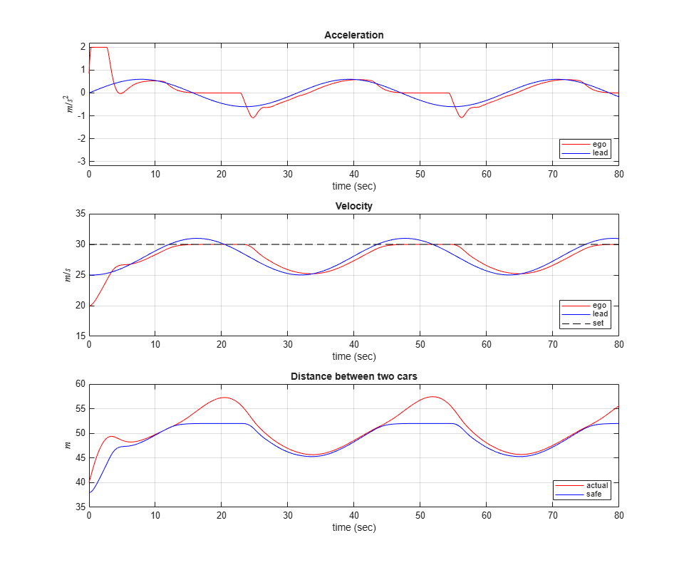
The total number of MFs for the I/O were determined based on how accurate the signal needed to be. Initially, each I/O had nine MFs to ensure enough range and accuracy were captured. During initial simulations, the run-time of the model was drastically increased due to there being 729 rules (9 MFs for 3 inputs) for the controller to evaluate when selecting a torque output for the system. Correcting this issue meant reevaluating how much weight each input should carry in the controller. At final competition, most events involved following a lead vehicle, so the MFs for the speed error input were reduced to 5, which meant a reduction to 405 total rules.

Final COmpetition Results
Upon further evaluation, it was determined that the relative speed could also be reduced to a total of 7 MFs which brought the total rules of the system down to 315, reducing the overall total to less than half of the first iteration. Faster computation time meant that the team could run multiple simulations over varying drive cycles to ensure the controller was performing at an optimum level and could track a specified speed or distance behind a lead vehicle. The output wheel torque command MFs were kept at a total of 9 to ensure proper torque commands when approaching a vehicle or launching the vehicle from a stop.
The end result of the students work in the final year of the EMC produced a controller that was capable of competing in all dynamic events and was deemed the most automotive-ready ACC algorithm by several subject matter experts at the competition, helping to secure a first place in the CAVs Drive Quality event. Zachary and I would like to extend a special thanks to Morgan Bartley, Erica Hall, and Murad Hamirani for their dedication to the creation and modification of the FLC.
- Category:
- Automotive,
- MATLAB


Comments
To leave a comment, please click here to sign in to your MathWorks Account or create a new one.