Skip to Main Content Skip to Search
File Exchange
MATLAB Newsgroup
Link Exchange
  Blogs  
 Contest 
MathWorks.com

Steve on Image Processing

September 25th, 2006

Dilation, erosion, and the morphological gradient

The morphological operator dilation acts like a local maximum operator. Erosion acts like a local minimum operator. You can use them together to compute something called the morphological gradient.

Contents

Dilation

The basic form of grayscale image dilation computes, for each image pixel, the maximum value of its neighboring pixels. The neighborhood is defined by the structuring element. For example, this structuring element:

se1 = strel([1 1 1])
 
se1 =
 
Flat STREL object containing 3 neighbors.

Neighborhood:
     1     1     1


defines a neighborhood consisting of the pixel itself, together with its left and right neighbors. Whereas this structuring element:

se2 = strel([1; 1; 1])
 
se2 =
 
Flat STREL object containing 3 neighbors.

Neighborhood:
     1
     1
     1


defines a neighborhood consisting of the pixel itself, together with the pixels above and below it.

Let's try dilation on everyone's favorite sample MATLAB matrix, the magic square:

m5 = magic(5)
m5 =

    17    24     1     8    15
    23     5     7    14    16
     4     6    13    20    22
    10    12    19    21     3
    11    18    25     2     9

d1 = imdilate(m5, se1)
d1 =

    24    24    24    15    15
    23    23    14    16    16
     6    13    20    22    22
    12    19    21    21    21
    18    25    25    25     9

d1(3,3), which is 20, is the maximum of [m5(3,2), m5(3,3), m5(3,4)], or [6 13 20].

Dilating with se2 computes the 3-pixel local maximum vertically:

d2 = imdilate(m5, se2)
d2 =

    23    24     7    14    16
    23    24    13    20    22
    23    12    19    21    22
    11    18    25    21    22
    11    18    25    21     9

d2(3,3) is the maximum of [m5(2,3), m5(3,3), m5(4,3)].

Erosion

Grayscale image erosion computes the minimum of each pixel's neighborhood.

e1 = imerode(m5, se1)
e1 =

    17     1     1     1     8
     5     5     5     7    14
     4     4     6    13    20
    10    10    12     3     3
    11    11     2     2     2

e1(3,3) is the minimum of [m5(3,2), m5(3,3), m5(3,4)].

Morphological gradient

Dilation and erosion are often used in combination to produce a desired image processing effect. One simple combination is the morphological gradient. P. Soille, in section 3.8 of the second edition of Morphological Image Analysis: Principles and Applications, talks about three kinds of basic morphological gradients:

  • dilated_image - eroded_image
  • original_image - eroded_image
  • dilated_image - original_image

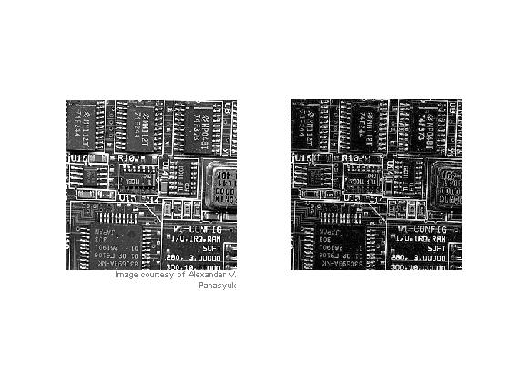
Soille calls the first one the basic morphological gradient, and you compute it this way using MATLAB and the Image Processing Toolbox:

% Read in circuit board image, crop it so it's not too big for the blog
% page, and convert it to grayscale:

rgb = imread('board.tif');
I = rgb2gray(rgb(1:256,1:256,:));

se = strel(ones(3,3));
basic_gradient = imdilate(I, se) - imerode(I, se);

subplot(1,2,1), imshow(I), imcredit('Image courtesy of Alexander V. Panasyuk')

subplot(1,2,2), imshow(basic_gradient, [])

The second form is called the half-gradient by erosion or internal gradient.

internal_gradient = I - imerode(I, se);

subplot(1,2,2), imshow(internal_gradient, [])

"The internal gradient enhances internal boundaries of objects brighter than their background and external boundaries of objects darker than their background. For binary images, the internal gradient generates a mask of the internal boundaries of the foreground image objects." [Soille, page 86]

The third form is called the half-gradient by dilation or external gradient:

external_gradient = imdilate(I, se) - I;
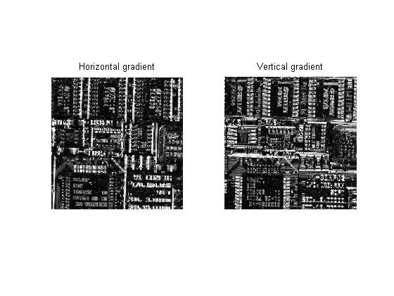
Direction gradients

By using line segments as structuring elements, you can compute directional gradients.

seh = strel([1 1 1]);
sev = strel([1;1;1]);

horizontal_gradient = imdilate(I,seh) - imerode(I,seh);
vertical_gradient = imdilate(I,sev) - imerode(I,sev);

subplot(1,2,1)
imshow(horizontal_gradient, []), title('Horizontal gradient')

subplot(1,2,2)
imshow(vertical_gradient, []), title('Vertical gradient')

Try this on your own grayscale images. You can experiment with larger structuring elements, too, such as strel('disk',7).

I'll be covering ways to combine erosion, dilation, and other fundamental morphological operators in the near future.


Get the MATLAB code

Published with MATLAB® 7.3

19 Responses to “Dilation, erosion, and the morphological gradient”

  1. vihang replied on :

    Can you please provide details of convex hull operation on an image.

  2. Steve replied on :

    Vihang - Are you talking about what regionprops does? For the ConvexHull option of regionprops, it first computes the perimeter pixels. Each perimeter has four corner points. regionprops calls convhull to compute the convex hull of the set of corner points of all the perimeter pixels. Does that help? See regionprops documentation for more information.

  3. Alex replied on :

    Would you please explain dilation and erosion with non-flat structuring elements on grayscale images? Thanks!

  4. Anubhav replied on :

    Sir i am working on plotting contours of back side of fingers and then find the length and width of finger. how should i find length and width of finger using matlab? i have tried doing it but problem is that image also contains some part of hand that is beneath fingers, so we have to make a reference point and thn only we can find the length. Can u please help me with it

  5. Steve replied on :

    Anubhav—Sounds like an interesting algorithm development problem, although maybe a little vague. But I don’t have any particular suggestions for you.

  6. pramod replied on :

    Sir,can u please explain how dilation and erosion done on grayscale images

  7. Steve replied on :

    Pramod—Oversimplifying a bit, dilation is a local max operator on some defined neighborhood of every pixel, and erosion is a local min operator. Sometimes there is also an additive offset applied to each pixel in the neighborhood before the max or min is computed. Details are plentiful in many image processing textbooks, as well as online.

  8. Michel replied on :

    We are processing holograms using your toolbox in our lab. Since holograms contain 3D information, it makes sense to do the image processing in 3D as well. The problem is that the 3D images matrices are huge, that the operations like imdilate and imerode take a long time and that it puts enormous demands on computer memory. The matrices contain however mainly zeros, so we decided to write some codes to do dilation and erosion based on the (x,y,z)-coordinates of the pixels. Our dilation code (fully vectorized) is faster than imdilate for small 3D structure elements, but is quickly outperformed by imdilate for larger ones. I’m now working on the (coordinate-based) erosion code, but I’m a bit clueless how to tackle it in preferably vectorized manner.
    Although the concept of dilation and erosion is simple, I’m puzzled as to how MATLAB does this so efficiently. Could you please explain how MATLAB performs dilation and erosion? If you have any ideas about performing these tasks on pixel coordinates only; I’m all ears. Many thanks in advance for your answer.

  9. Steve replied on :

    Michel—I’ve had dilation and erosion algorithms on my blog topics list for a long time, but I’ve been procrastinating because it’s a complex story. There are several different algorithms used in a complementary way by imdilate and imerode: Structuring element decomposition, binary word packing, and a special method just for horizontal and vertical line structuring elements.

    In your comparisons, are you using a rectangular structuring element? For that case, our combination of algorithms achieves a running time that is independent of the structuring element size.

    For other shapes, you could be seeing the effects of our other structuring element decompositions.

    Note also that there’s a lot C code underlying our morphology implementations. See the source code in toolbox/images/images/private/.

  10. Suresh replied on :

    I am trying to use morphological operators for one dimensional signal (e.g. sinusoidal signal with random noise).

    For the initial start, I am trying to visualize the process manually using a vector representing a signal (eg input signal, x=[1,1.3,1.6,1.4,1.6] and structuring element, g=[0,1,0]). I used the following expression for dilation.

    dil(x)=max{x(n-m)+g(m)}, n-length of IP signal,m-length of SE

    I get different result when I calculate it manually and when I use matlab to do so.

    Is it possible to know how matlab handles this expression? Or what algorithm matlab uses?

    Thanks in advance.

    Suresh

  11. Steve replied on :

    Suresh—You didn’t say how you were computing the dilation in MATLAB, and your formula is incomplete, but I have a guess about what your problem might be. Perhaps you are using this syntax for imdilate:

      y = imdilate(x, [0 1 0]);
    

    With this syntax, the 2nd argument specifies the domain of a flat, zero-valued structuring element. Since only the center element of your domain is nonzero, your structuring element has only a single element in it, and the output is the same as the input.

    To specify and use nonflat structuring element, you need to do this:

      se = strel('arbitrary', [1 1 1], [0 1 0]);
      y = imdilate(x, se);
    
  12. Suresh replied on :

    Steve,
    Thank you for the reply. I appreciate your help.
    Your suggestion worked but I still get error in one of the element. Here is what I got using matlab,

    >> x=[1,2,4,6,-20,3,1];
    >> se = strel(’arbitrary’, [1 1 1], [0 1 0])
    >> y = imdilate(x, se)

    y =

    2 4 6 7 6 4 3

    But this is what I get manually,
    y = [1 2 4 6 7 6 4]

    The example quoted above (plus manual solution) is taken from a paper [X. Lin, H. Liu, H. Weng, P. Liu, B. Wang, and Z. Q. Bo, Senior Member, IEEE “A Dual-Window Transient Energy Ratio-Based Adaptive Single-Phase Reclosure Criterion for EHV Transmission Line”, IEEE Transactions on Power Delivery, Vol. 22, NO. 4, pp.2080-2086, October 2007].

    Also I have some papers, (not quoted here to make shorter) which say that Structuring Elements can be semi-circular, triangular or even sinusoidal with real numbers as its element. But Matlab documentation says SE consists of only 0 and 1. Is there any way to deal with this case in matlab?

    Thank you
    Suresh

  13. Steve replied on :

    Suresh—It looks to me like your result is simply shifted by one position. Note that the Image Processing Toolbox is for the center of the neighborhood matrix is the origin. Your paper and your manual computations are probably using a different convention.

    MATLAB documentation does not say that the structuring element consists of only 0s and 1s. The structuring element neighborhood (or domain) input is 0s and 1s. As I mentioned in my previous response, to create a nonflat structuring element you should use this syntax:

    se = strel('arbitrary', nhood, height)
    
  14. alice replied on :

    Hello, Steve,

    I tried to do binary expansion with bwmorph. The test.m file contains
    mask = zeros(12, 12);
    mask(5:7, 5:7) = 1;
    mask = bwmorph(logical(mask), ‘dilate’);

    It works well in matlab script. There was also no error when I compiled test.m with mcc -m -B sgl -T link:exe test.m. However, executing !test.exe yields
    “Warning: Duplicate directory name: c:\matlab6p5\toolbox\matlab\iofun.
    ERROR: Reference to unknown function ‘checknargin’ from FEVAL in stand-alone mode.

    EXITING ”

    Could you please advise how to resolve this problem?

    Thanks a lot!
    Alice

  15. Steve replied on :

    Alice—See this support note.

  16. alice replied on :

    Thanks, Steve

    Yes, it was the compiler’s problem. I have tried the solution on Matlab v7.1 R14 and it works!

    Thanks for your help.

    Alice

  17. dewi replied on :

    Sir, coulf you tell me about how erotion and dilation work in segmentation of an image??

    I’m making a face detection and now I’ve segmented the RGB image using the intensity. I want to know what method you would like to recommended that gives optimum automated threshold value? is it using dilation/erotion, using Otsu,or something else?

    Thank you so much..

  18. Steve replied on :

    Dewi—The function graythresh, which uses Otsu’s method, does a pretty good job of automated threshold selection.

  19. dewi replied on :

    Thank you so much Sir…
    I’ll try the graythresh function.

Leave a Reply


Steve Eddins manages the Image & Geospatial development team at The MathWorks and coauthored Digital Image Processing Using MATLAB. He writes here about image processing concepts, algorithm implementations, and MATLAB.

  • ismail: i love chess keep posting :) can we make a web cam identify a chess set ? so we have a roboarm plays for real...
  • Navan: While black is going to win with a smothered mate, it is hard to see what moves would have led to this...
  • Doug: Forced ’smothermate&# 8217; is about to happen, with the added insult of threatening the queen on the...
  • Viton: Let’s give it a try: - RxQ : White Rook takes black Queen (White King was checked, can’t take...
  • Omar: Hi Steve, when using tformfwd to find corresponding points in the new space, the resulting co-ordinates from...
  • Steve: Cris—You’ ;re right, I should have caught the plot scaling issue. I wasn’t actually trying...
  • Cris Luengo: Not to spoil your upcoming bog entry too much, but if you scale the first graph (times vs Q) by setting...
  • Steve: Jim—Thanks for adding your comment showing how the syntax works for matrices.
  • Jim: for i = A …statements 230; end; Description: The …statements 230; are executed (as MATLAB...
  • Steve: Omar—Nice work.

These postings are the author's and don't necessarily represent the opinions of The MathWorks.

Related Topics