
Team Automatons Builds a Quadruped Robot for the ABU Robocon 2019 Task
For today’s post, I would like to introduce you to Team Automatons from Pimpri Chinchwad College of Engineering, Pune. They recently scored 2nd in the MathWorks Modelling Award at the National DD-Robocon 2019, New Delhi. The team will share their experience of using MATLAB and Simulink for their quadruped design. Thanks very much and the stage is yours!
—
Hey! We are Team Automatons from Pimpri Chinchwad College of Engineering, Pune. Before we start explaining the technical details of our work, let us show you what we have done.
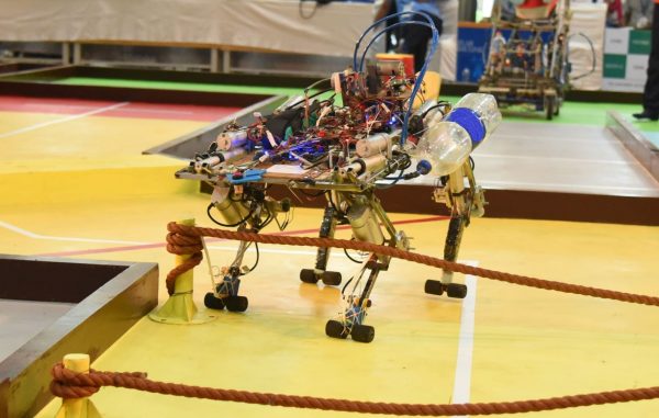
As you can see, we have built an autonomous quadruped to compete in the ABU Robocon 2019 competition that can walk on plane terrain, overcome obstacles, cross series of ropes, and climb mountains.

Having seen some cool operations by our quadruped, it becomes clear that it was a complex project. On top of that, we had only 5 months with a limited amount of fund.
In general, there are various gait patterns such as trot, walk, gallop, pace, etc. One of the major challenges was to decide the type of gate cycle. So, let us see how we were able to overcome this challenge using MATLAB and Simulink.
Inverse Kinematics
To find the relation between the trajectory of the end-effectors and the joint angles of the quadruped we have two methods: Forward kinematics and inverse kinematics. Inverse kinematics includes the position of end effectors as inputs and joint angles as the output. We assumed the end effector to follow a half ellipse path and calculated the angles at the hip and knee joint using Inverse kinematic analysis. We used the following equations for the joint angles:


Further, these equations were used to build the inverse kinematics model of the robot. The equations were implemented using MATLAB function blocks and some basic Simulink blocks. The output ports, “Knee” and “Hip” specifies the joint angles.

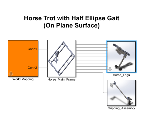
Integration of Inverse Kinematics model and CAD assembly
Once the inverse kinematics models were ready, we built a CAD assembly of the quadruped in SolidWorks and then imported it into MATLAB by enabling Simscape Multibody link SolidWorks plug-in. After importing the model, necessary joints from Simscape Multibody were added to the model. Finally, the output of the inverse kinematics model was connected to the respective motion input of the revolute joints.

Contact Force Implementation
To move the quadruped in the simulation arena, it is necessary to include the relation between the joint angles of the legs and the COG of the quadruped. Hence, the next step would have been to include the relation in the model. However, we decided to use the Simulink Contact Forces library which provided the friction between the foot and the ground to move the quadruped.

There are various contact force blocks available in the library. In each one of them, the values of stiffness, damping, coefficients of static, and kinematic friction can be specified. Finally, we simulated the model for various gait patterns and found that the trot gait cycle is the most stable one.


Implementation on the Quadruped
In the actual quadruped robot, we used the potentiometer to measure angular feedback. These sensor readings provided us the values for maximum and minimum angles. Finally, to verify the simulation model, the measured angles were compared with that obtained by the potentiometer.
The coordinates of the foot for various walking patterns such as walking, crossing a sand dune, etc. were obtained by simulating the model and the same values were used on the quadruped. The initial simulation results showed that the motion of the quadruped was not stable because of the vibration in the legs. Similar behavior was seen during actual walking of the quadruped. To overcome this problem, we moved the pivot point of the leg inside the body and the C.G was balanced. Then, the height of quadruped was reduced by almost 30 cm and the simulation results were studied. After obtaining the desired motion of the quadruped, accordingly, the design was changed.
As stated earlier, the maximum and minimum achievable angles of the quadruped along with potentiometer readings for these positions were calculated. These values were stored in the code and were used to get the potentiometer readings at various positions by mapping the angles obtained from inverse kinematics formula against the maximum and minimum values.
Conclusion
Simulating the quadruped helped us to understand the design requirements, to find successfully implement walking, and to verify various parameters. The use of MATLAB for acquiring data from sensors helped in visualizing and analyzing it further.
We are thankful for the various video tutorials available on MATLAB and Simulink Racing Lounge and MATLAB and Simulink Robotics Arena. Special mention to the Walking Robot videos which provided the step by step procedure to model a robot using Simscape Multibody. The models available on the MATLAB File Exchange helped us a lot in developing our own models.
On a side note, if you are interested in further discussion or if you have any queries please reach out to us at automatons.robotics@gmail.com. You can also join our Facebook and Instagram group.


Comments
To leave a comment, please click here to sign in to your MathWorks Account or create a new one.