
An Autonomous Quadruped Manipulator for Pick and Place Applications
For today’s post Roberto Valenti, who leads the MathWorks Challenge Project program will talk about a senior design class project at University of Sheffield. Over to you, Roberto…
At the University of Sheffield’s campus, a team of eight motivated students enthusiastically embraced a real-world project as part of their senior design class. Motivated by their shared interest in robotics and a desire for gaining practical experience, they tackled an ambitious challenge project that would not only push the boundaries of their technical skills but also prepare them for promising careers in the field of autonomous robotics. The project is from the MATLAB and Simulink Challenge Project Hub, a platform that aims to bring together academia and industry to encourage innovation and bridge the gap between academic education and real-world applications.
Figure 1: The Team. From left to right: Serena Cicin-Sain, Olivia Organ, Will Foster, Joseph Moore, and Sherif Sawwaf. Not present in the picture: Harry Armstrong, Oluwaseun Adewola,and Josh Orme-Herbert
“This project has proven to be immensely valuable as it allowed us to comprehensively navigate an entire project lifecycle, engaging in all facets, including research, design, integration, and project management, all while adhering to a Systems Engineering approach. The endeavor presented significant challenges, necessitating the group to proactively demonstrate initiative through extensive research and innovative problem-solving. A team member capitalized on this experience to demonstrate their skills to potential employers, securing a job in an engineering role. The project, marked by its challenges, has also been enjoyable and rewarding, particularly given the positive feedback we have received. Our group takes considerable pride in our collective accomplishments, recognizing that it was our unwavering determination and seamless teamwork that made it all possible. We extend our sincere gratitude to our supervisor, Payam Soulatiantork, and Roberto Valenti from MathWorks, both of whose invaluable knowledge and guidance were indispensable to the project’s success”.
Take a look at the students’ submission GitHub repository  .
.
Introduction
The selected challenge project required the team to design, model, and simulate an autonomous quadruped robot equipped with a robotic manipulator to perform sophisticated pick and place tasks. To effectively accomplish this challenge the team organized itself into four sub-teams, each working on one of the four subsystems: quadruped, manipulator, navigation, and perception. Work done on each subsystem by a specific team was integrated into a single autonomous robotic system in which a high-level state machine commands each task of the robot while keeping track of the system state. During the project development phase, efforts were coordinated and supervised to ensure timely completion while prioritizing tasks and member responsibilities to meet the predefined requirements. Risk assessments were also factored in to mitigate potential challenges.
Quadruped modeling and simulation
The quadruped sub-team designed a robot replicating animal gaits, focusing on a diagonal advanced placement akin to dogs and horses. Their design featured four legs with three links and joints, ensuring coordinated movement within a one-cubic-meter volume. This design allowed efficient locomotion and balance, including a stable stationary gait. The team’s inspiration from animal locomotion principles enabled effective movement of the robot and led to successful implementation. The team began with a
Simscape™ Multibody™ model of a quadruped limited to forward motion in the horizontal plane. Their goals included: adding a shoulder joint for omnidirectional movement, designing control systems for joint actuation, and creating a walking plan with tailored gait phases for complex turning maneuvers.
The team explored different motion control strategies, including the Inverse Kinematic strategy and the Raibert strategy. The Raibert strategy uses a dynamic quadruped motion control model that splits the robot’s control into velocity, body rotation, and hopping height components, resulting in a dynamic trotting gait model. This approach was adopted due to its simplicity and functionality and implemented using a high-level Stateflow® controller that integrates various walking and turning states of the quadruped into the final system.
Once the quadruped successfully achieved turning movements while maintaining stability, the team implemented a high-level Stateflow task planner for enhanced navigation. This task planner determines the quadruped’s movement mode (stationary, walking straight, turning left, or turning right) based on the relative angle and distance to the target coordinates, enabling effective navigation and obstacle avoidance. A demonstration of the quadruped locomotion including a visual of the walking controller and the high-level task planner is shown in Figure 2.
The successful implementation of a stable walking and turning control algorithm, was a critical achievement for the quadruped project and served as a foundation for integrating the other subsystems.
Figure 2: Quadruped walking gait demonstration. (Top) High-Level Stateflow diagram for motion mode transition and execution, (Bottom Left) Stateflow walk cycle for the Raibert strategy mode, (Bottom Right) Quadruped 3D visualization.
Manipulation
The manipulator sub-team adopted a Kinova Gen3 robotic manipulator for this project. The manipulator model was scaled using CAD software to meet the project requirements and the URDF files were then loaded into MATLAB® for creating a Simscape model with bodies and revolute joints. A closed-loop control system with PI control was implemented for each joint to ensure smooth and precise movement.

Figure 3: The end effector. (Left) Simscape model, (Right) full manipulator with attached the end effector.
To enable object interaction, an end effector with three fingers was attached to the manipulator. The end effector has two revolute joints per finger, as shown in Figure 2, allowing it to mimic human fingers and securely grasp objects. Inverse kinematics calculations were performed using a rigid body tree and forward kinematics models. A forward kinematics model was generated to determine the position and rotation of the end effector based on the joint angles. An inverse kinematics solver utilizing the Broyden-Fletcher-Goldfarb-Shanno (BFGS) Gradient Projection algorithm was implemented to find the joint angles required to reach a given transform.
A high-level controller facilitates object picking within the defined environment. The manipulator subsystem (Figure 4) includes a state variable for communication between the quadruped and manipulator. This variable determines when the quadruped is positioned next to the object or the desired end position.
The manipulator task planner manages the order of operations and ensures that the manipulator reaches the correct position before proceeding. It coordinates the movements of the manipulator joints and monitors the states of all subsystems.
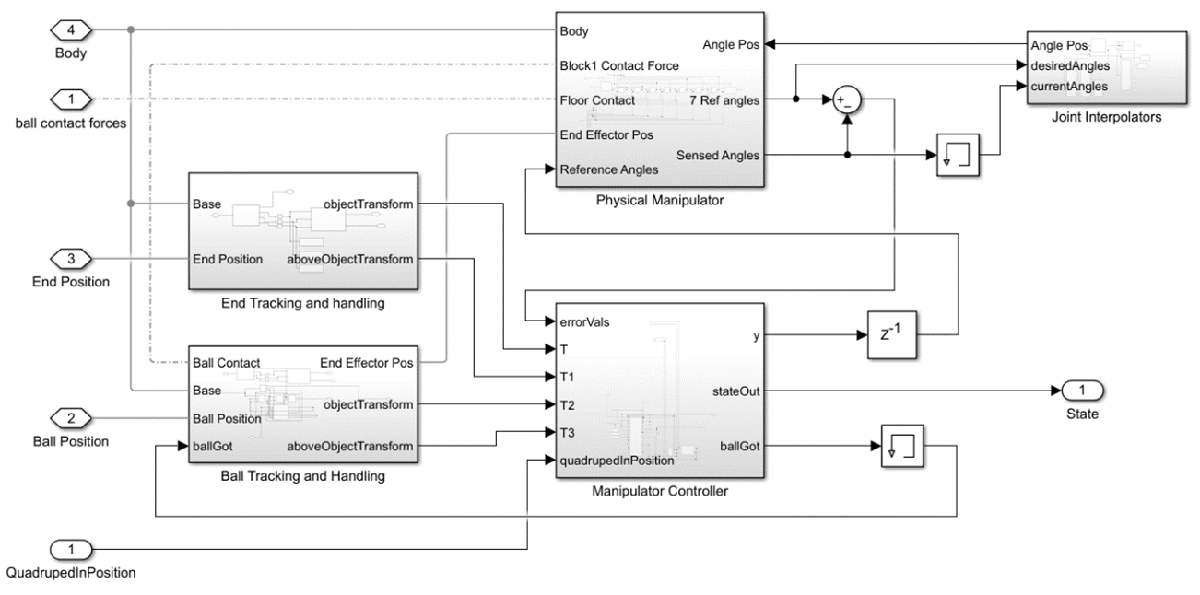
Figure 4: The full manipulation subsystem model.
With the manipulator subsystem implemented, the manipulator is able to pick up objects within the environment. The end effector, equipped with three fingers, curls around an object to secure it in place. Contact forces between the floor, object, and manipulator were simulated for realistic interactions. A complete pick and place task of the manipulator subsystem is shown in Figure 5. The manipulator subsystem was integrated with the quadruped, allowing communication between them.
Figure 5: A ball picking demonstration.
Navigation
The navigation sub-team adopted the RRT* algorithm for path planning, enabling the quadruped to navigate through user-defined environments. The RRT* algorithm optimized paths for efficiency, combining two planned paths, namely start to pick-up and pick-up to drop-off, into one array as shown Figure 6.
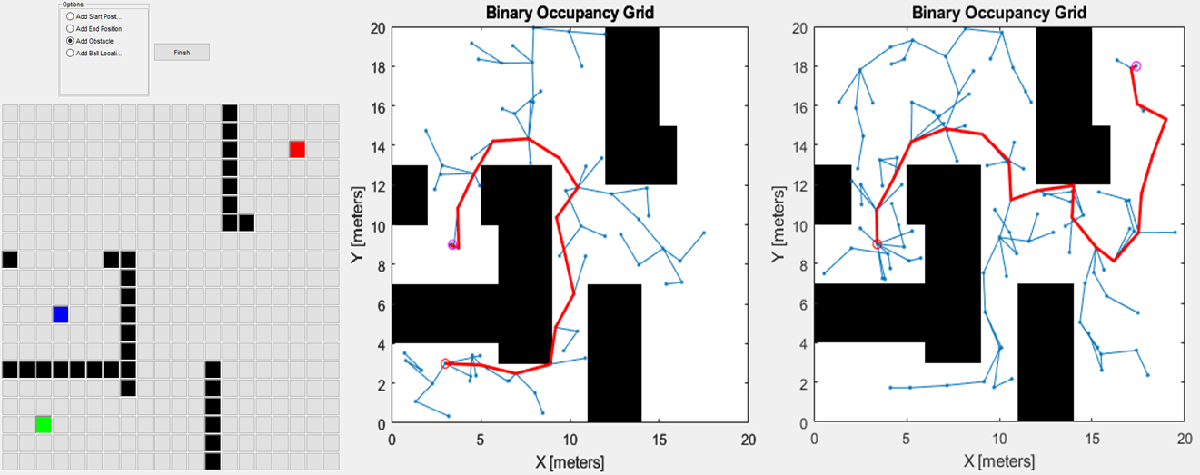
Figure 6: (left): Functional GUI with start, pick up and place locations, and obstacle blocks, (middle): occupancy grid path from start to object pick-up position, (right): occupancy grid path from pick-up to end place.
The environment model was constructed in Simulink® based on a Graphical User Interface (GUI) input. The GUI allows intuitive placement of start and end points, obstacles, and pick-up locations, forming a visual representation of the environment. Rigid transform blocks position the quadruped, ball, and podium accurately based on this environment model. Figure 7 demonstrates the user’s interaction with the GUI, illustrating the creation of an environment map and object placement, followed by automatic generation of the 3D scenario and a navigation path.
Controller optimizations included replacing PID controllers with 1-D lookup tables for manipulator joints, ensuring smoother manipulative actions, and implementing a feedback-based braking system to fix the ball securely to the manipulator’s palm. The high-level control logic was managed by the task planner implemented in Stateflow, which orchestrates tasks such as path following, ball pick-up, placement, and simulation termination.
Figure 7: A demonstration of a user interaction with the GUI: Creating an environment map, placing objects, and triggering automatic generation of a 3D scenario and navigation path.
Integration
In the final stages of the project, the team achieved seamless integration of various subsystems to create a functioning autonomous robotic system. The Simulink model illustrating this integration is presented in Figure 8. The GUI played a pivotal role in generating intricate maps and setting waypoints. The Path Planning subsystem, coupled with a Target Selector, enables the quadruped to navigate precisely, ensuring it follows the designated path accurately.
The Path Follower Stateflow module makes real-time decisions based on inputs from the Target Selector and the Angle and Distance Finder. It orchestrates intricate movements, including turns, halts, and forward strides, ensuring the quadruped’s adherence to the predefined route.
At the core of this integration, the Task Controller Stateflow oversees the entire process. It monitors the position index, ensuring the quadruped reaches each waypoint as planned. Additionally, it manages the initiation of complex tasks like picking up and dropping off the ball, synchronizing these actions seamlessly within the overall movement plan.
The Quadruped Movement Controller plays a crucial role in executing precise joint movements. These movements are meticulously calculated to maintain balance and stability, ensuring the quadruped’s movements are both accurate and secure.
The strategic placement of the manipulator at the quadruped’s enables a balance between stability and functionality, allowing the manipulator to perform tasks efficiently without compromising the quadruped’s stability during locomotion.
This detailed integration process highlights the team’s technical expertise, showcasing their learnings in system integration that turns subsystem elements into a unified and operational robotic system. Figure 9 shows a simulation of the final integrated model of the full system in action.
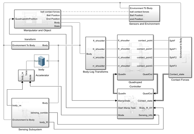
Figure 8: The full system Simulink model
Figure 9: The full system in action.
Conclusion
Working on this Challenge Problem provided the team with an opportunity to learn several real-world skills. They learned how to break down a large complex robotics problem into smaller subsystems, design and implement those subsystems, and integrate them into an overall functioning system. Throughout this approach, modeling and simulation enabled them to design their functionality in such a way that met the high-level requirements.


Comments
To leave a comment, please click here to sign in to your MathWorks Account or create a new one.