Spatial transformations: Where is the output image?
I wrote previously that most spatial image transformation implementations use inverse mapping. The Image Processing Toolbox function imtransform is implementated using this technique.
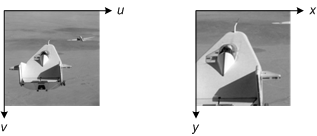
Here's an interesting issue that arose during the design of imtransform: How does it know where the output image is located in the x-y plane? In other words, in the inverse mapping diagram below, how does it know exactly where the output grid should be?

There are three basic problems you can have with the output grid. It can be too small; it can be too big; or it can be in the wrong place entirely. I'll illustrate these situations with an output grid that is the same size as the input grid, and that is also in the same place.
In the first example, the spatial transformation magnifies the input image. The output grid doesn't cover enough territory in output space to capture the entire transformed image.

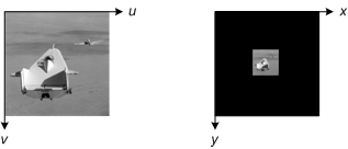
In the next example, the spatial transformation shrinks the input image. As a result, the output grid covers too much territory. The black output pixels below are output image pixels that aren't needed to capture the entire transformed image.

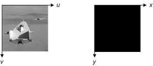
In the final example, the spatial transformation moves the input somewhere else. Maybe the transformation is simply a 1000-pixel horizontal translation. In this situation, the output grid doesn't contain any of the transformed image!

When we were designing imtransform, we thought that any of these scenarios would likely result in frustrated users calling tech support. We tried to avoid this by making imtransform do "the right thing."
Next time, I'll describe the calculation imtransform does to automatically produce the results expected by users. (Almost all the time, that is.) If you want a preview, take a look at the function findbounds.


댓글
댓글을 남기려면 링크 를 클릭하여 MathWorks 계정에 로그인하거나 계정을 새로 만드십시오.