
Registering Hand-Held Pictures
The typical modern French* horn, pictured below, has about 23 total feet of tubing. At the beginning and the end, the tubing is conical. In the middle, the tubing is cylindrical.
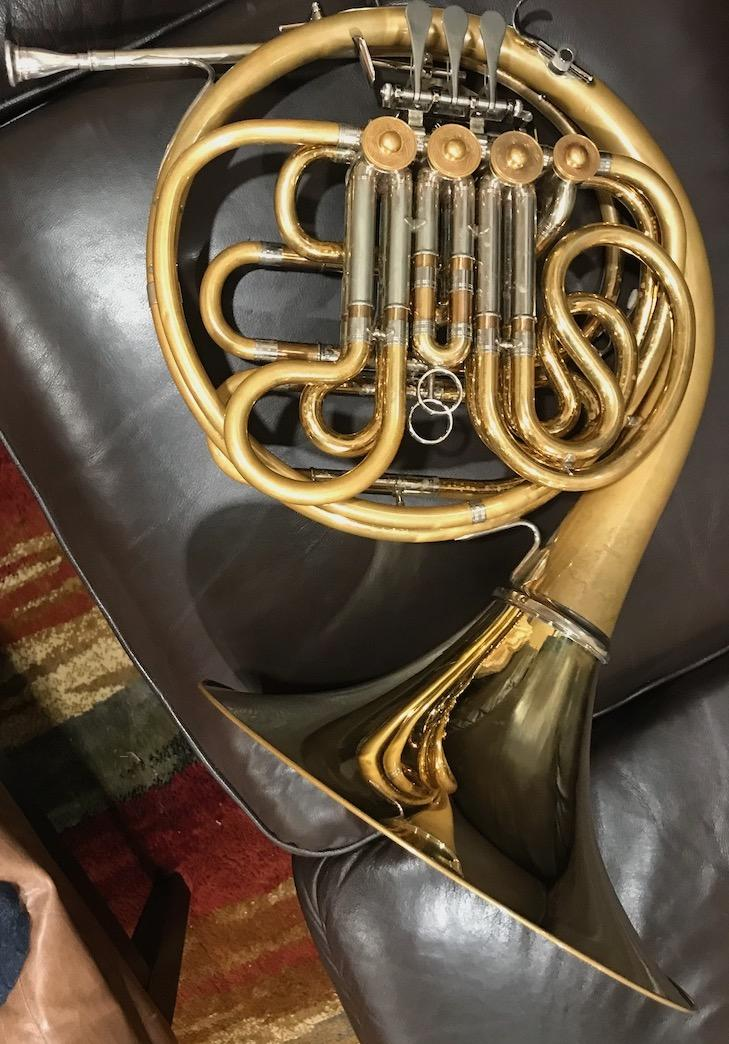
Depending on which valve levers are pressed, a player might be buzzing into single tube that is anywhere from 9 feet to 17 feet long (approximately). For a personal project, I wanted to create a visual illustration of these various lengths. I used an extension pole and got some help in taking several pictures. My helper used a handheld phone.
A = imread('A.jpg');
B = imread('B.jpg');
C = imread('C.jpg');
tiledlayout(2,2)
nexttile
imshow(A,'Interpolation','bilinear')
title('Image A (length of F horn, 12 feet)')
nexttile
imshow(B,'Interpolation','bilinear')
title('Image B (length of B-flat horn, 9 feet)')
nexttile
imshow(C,'Interpolation','bilinear')
title('Image C (length of B horn, 17 feet)')
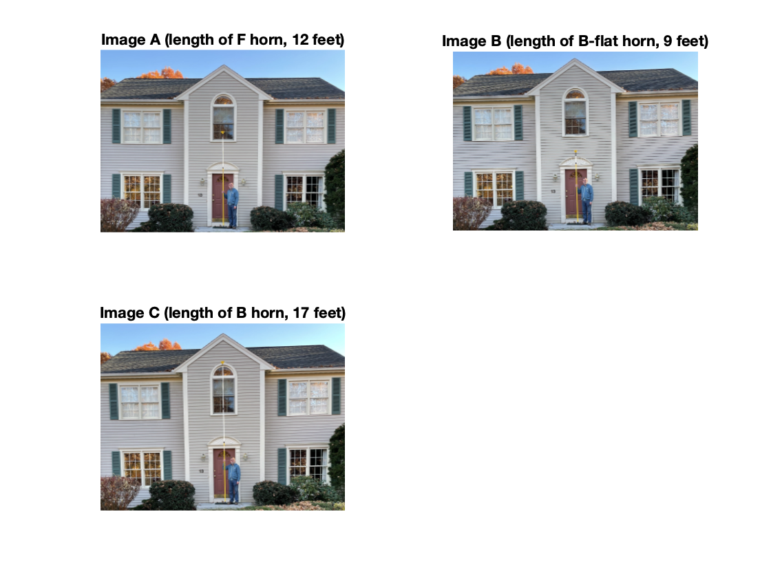
I wanted to use these pictures to make a composite that lets you visually compare the three pole lengths. The problem is that these three pictures aren't aligned with each other, which makes creating an accurate composite challenging.
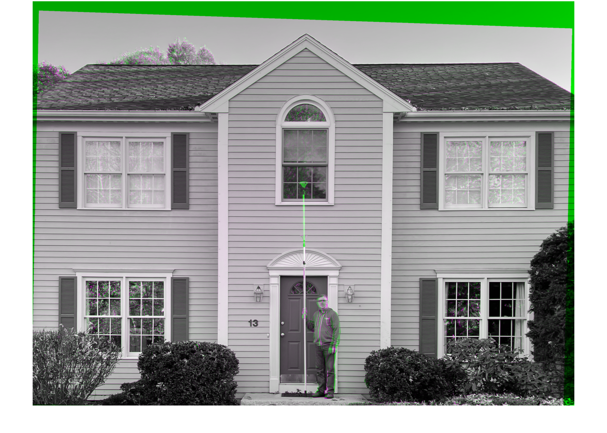
Let me use imshowpair to illustrate what I mean, using images A and B.
clf
imshowpair(A,B)

It looks like these two images differ from each other by a translation and a small rotation.
To accomplish my goal, then, I need to get these three pictures aligned with each other first. Then I can crop them and create my composite.
Sounds like an image registration and spatial referencing problem!
Here's the plan:
- Infer a geometric transform that aligns image B to image A.
- Infer a geometric transform that aligns image C to image A.
- Using the transforms found above, warp images B and C to the same spatial reference as image A.
- Crop all three images closely around me holding the pole in the center.
- Create a composite of the three images.
I'll be using tools in the Image Processing Toolbox and the Computer Vision Toolbox.
Register image B to image A
Convert images to grayscale for the registration procedure.
Ag = rgb2gray(A);
Bg = rgb2gray(B);
Use SURF feature detection (from the Computer Vision Toolbox) in both images.
% Detect SURF features
A_points = detectSURFFeatures(Ag);
B_points = detectSURFFeatures(Bg);
Extract feature info from the detected feature points.
[A_features,A_valid_points] = extractFeatures(Ag,A_points);
[B_features,B_valid_points] = extractFeatures(Bg,B_points);
Match up the feature points from the two images.
index_pairs_B_A = matchFeatures(A_features,B_features);
A_matched_points = A_valid_points(index_pairs_B_A(:,1));
B_matched_points = B_valid_points(index_pairs_B_A(:,2));
Infer a projective geometric transformation that will align image B with image A.
tform_B_A = estimateGeometricTransform(B_matched_points,A_matched_points,'projective');
tform_B_A.T
Align image B to image A. Note especially the use of the OutputView option of imwarp; this is used to compute the image warping result exactly in the same spatial rectangle as occupied by image A.
A_ref = imref2d(size(Ag));
B_reg = imwarp(B, tform_B_A, 'OutputView', A_ref);
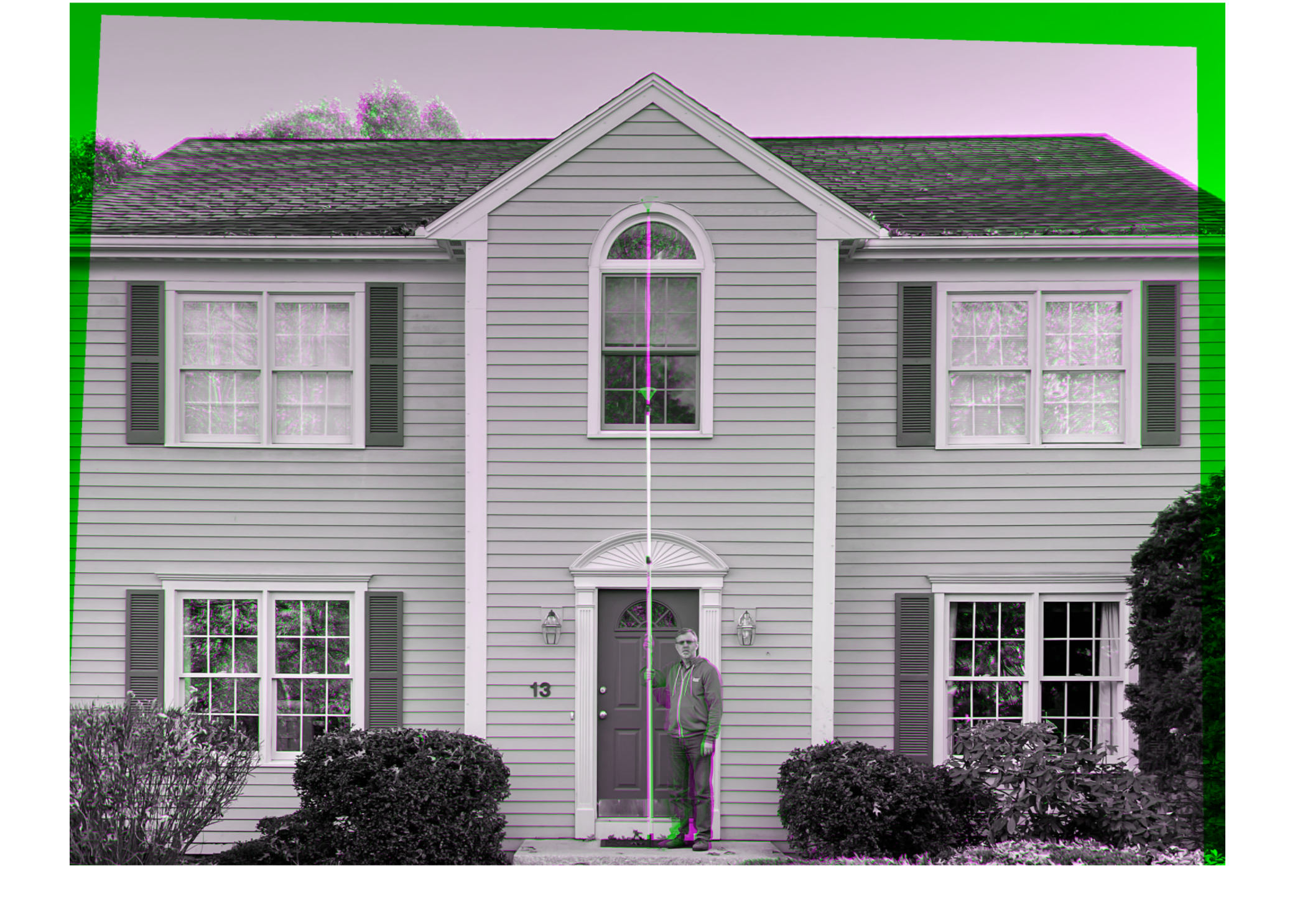
Visually check the result.
figure
imshowpair(A,B_reg,'Interpolation','bilinear')
Register image C to image A using the same procedure
Cg = rgb2gray(C);
C_points = detectSURFFeatures(Cg);
[C_features,C_valid_points] = extractFeatures(Cg,C_points);
index_pairs_C_A = matchFeatures(A_features,C_features);
A_matched_points = A_valid_points(index_pairs_C_A(:,1));
C_matched_points = C_valid_points(index_pairs_C_A(:,2));
tform_C_A = estimateGeometricTransform(C_matched_points,A_matched_points,'projective');
C_reg = imwarp(C, tform_C_A, 'OutputView', A_ref);
imshowpair(A,C_reg,'Interpolation','bilinear')
Crop images to a common rectangle
Now that images A, B, and C have all been registered to the spatial reference of image A, they can all three be cropped using the same rectangle in the same position.
r = [1100 450 600 1600];
A_c = imcrop(A,r);
B_reg_c = imcrop(B_reg,r);
C_reg_c = imcrop(C_reg,r);
Make a tiled composite
Finally, I'll use imtile to make a tile composite image that can be saved to a JPEG file.
ABC = imtile({B_reg_c,A_c,C_reg_c},...
'BorderSize',50,...
'BackgroundColor','white');
imshow(ABC,'Interpolation','bilinear')
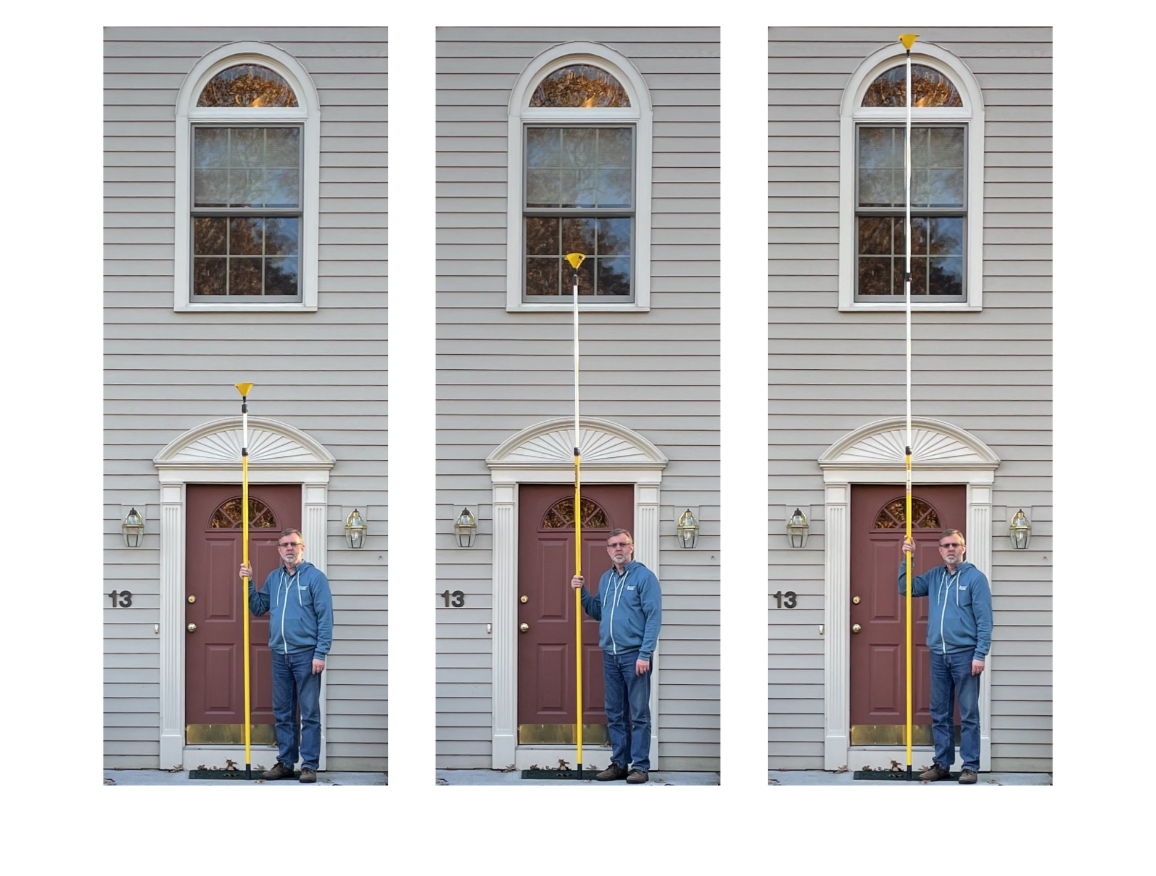
It amazes me that this instrument that I can hold in my lap can really be a tube as long the pole pictured on the right.
* The modern instrument is not French in origin, so French horn is a misnomer, strictly speaking. Many players refer to the instrument simply as a horn, and this is the recommendation of the International Horn Society. In the United States,however, most people who are not orchestral musicians will be confused by the term horn, and so I use French horn here.


Comments
To leave a comment, please click here to sign in to your MathWorks Account or create a new one.