 Cleve’s Corner: Cleve Moler on Mathematics and Computing
 The MATLAB Blog
 Guy on Simulink
 MATLAB Community
 Artificial Intelligence
 Developer Zone
 Stuart’s MATLAB Videos
 Behind the Headlines
 File Exchange Pick of the Week
 Hans on IoT
 Student Lounge
 MATLAB ユーザーコミュニティー
 Startups, Accelerators, & Entrepreneurs
 Autonomous Systems
 Quantitative Finance
 MATLAB Graphics and App Building
How to Efficiently Customize Vehicle Dynamics Models for Formula Student Competitions
For today’s blog, we are happy to host Huang Huateng, the technical leader of the electric fleet of South China Agricultural University. His team won the first prize in the MATLAB/Simulink vehicle dynamics simulation and second prize for the control strategy development and software implementation.

Introduction and Motivation
In the process of developing vehicle dynamics models for FSAE events, we have encountered the following common problems:
- Failure to build a high DOF vehicle dynamics model
- Low efficiency when customizing vehicle dynamics models
- Coupling multiple subsystems to build a full vehicle model
After several seasons of exploration, we decided to go ahead with the reference applications available in the Vehicle Dynamics Blockset and Powertrain Blockset. In the subsequent paragraphs, we will briefly share our experience of using these reference applications.
One of the issues when customizing a vehicle dynamics model is efficiency. If you use basic modules based on theoretical knowledge or write custom modules to build the entire model from scratch, it takes a large amount of work. Moreover, in terms of our team’s experience, this approach often spends a lot of time debugging the model. In this case, the advantages of customization are overshadowed by efficiency issues.
Therefore, our team prioritizes using the existing modules in the relevant toolbox, which are more reliable. We only need to understand the module principle and input and output signals referring to the documentation and judge whether it meets our needs. For our event, the two most important toolboxes are Vehicle Dynamics Blockset and Powertrain Blockset. The reference applications provided in these two toolboxes are basically enough to support us to complete the core part of a vehicle dynamics model, including engine/motor, driving system, powertrain, steering system, and braking system. Learning to leverage the relevant reference applications helped us to accelerate the speed of our custom vehicle model.
Case Study
Reference base model
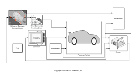
In the process of building a model, we should only select some important objects in the whole vehicle, and also consider the connection mode and hierarchical design between the various systems. This makes it easy for students who have just started with modeling and simulation. Many case models that Simulink comes with, as well as vehicle models provided by online competitions, are the best learning resources. We also recommend vehicle dynamics models developed and customized based on these models. In our case, we took one of the case models as an example. For example, as a starting point, we referred to the Constant Radius Reference Application.
Model modifications
At the beginning of the season, based on experience and theoretical calculations we determined some vehicle design parameters such as gear ratio, wheelbase, aerodynamic parameters, etc. These parameters were used in the Simulink vehicle dynamics model to investigate the impact on the vehicle performance, stability analysis, and to perform lap time simulations.
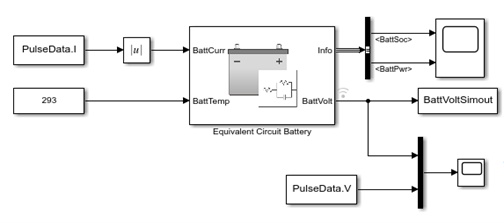
Further, we utilized the above reference application to perform the simulations. We deleted the gearbox, differential, and other related parts and added a motor and a battery model. The battery model was based on the discharge experiment data and was obtained through the method of parameter identification. The figure below shows the equivalent circuit battery model we used. In this way, our vehicle model was able to stimulate the economy and verify the energy recovery strategy.
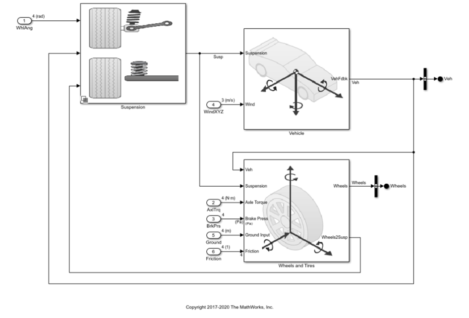
Next, we utilized the suspension system architecture as provided in the base model and parameterized the model as per our vehicle data. Hence, we were able to customize the vehicle dynamics model in a short time ensuring efficiency and reliability. Of course, this approach must be based on understanding the original case model.
Next, we needed to optimize the effect of the control strategy through some feedback data from real vehicle tests. For the same, we built a custom subsystem to control the torques at the rear wheels and integrated it with the base model.
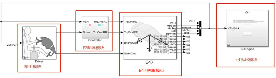
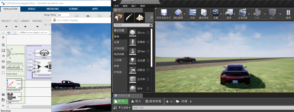
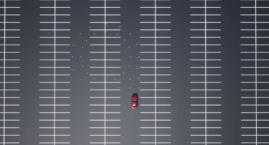
Finally, to visualize the vehicle in 3D, we used the prebuilt scenes in Vehicle Dynamics Blockset created with the Unreal Engine®, a game engine developed by Epic Games®. From our experience, the 3D visualization of the vehicle dynamics model is a high degree of integration and visualization of a large number of simulation results, including vehicle speed, attitude angle, vehicle trajectory, etc., so that we have more time to verify the vehicle dynamics model. The following figure shows the operation interface of the Unreal Engine Editor. We modified one of the prebuilt scenes by placing cones by the rule of figure eight (only the left circle is placed).
GUI design
When we iteratively optimize vehicle design parameters or control strategies, we generally use different parameters and switch between different working conditions for multiple simulations. This can be time-consuming and difficult for other team members to use the model. Hence, we developed an app using MATLAB App Designer that lets you create professional apps without having to be a professional software developer. This streamlined our iteration process, improved the efficiency of existing code to integrate and enhance human-computer interaction, and gave easy access to parameterize the model.
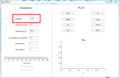
The figure below is our GUI. We can directly fill in the value in the red box to set the gear ratio of the reducer.
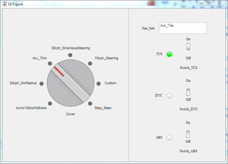
In addition, you can switch between various preset working conditions by rotating the knob, and directly set the on/off of various control strategies through the buttons on the right, as shown inthe figure below.
Using MATLAB App Designer to develop such a GUI is a thing whose learning cost is far lower than the benefit. The main reason is that this tool not only provides a graphical operation interface but also provides a lot of auxiliary functions for code writing. Therefore, you can quickly get started to make a practical GUI by exploring the reference examples that come with this tool.
Outcome
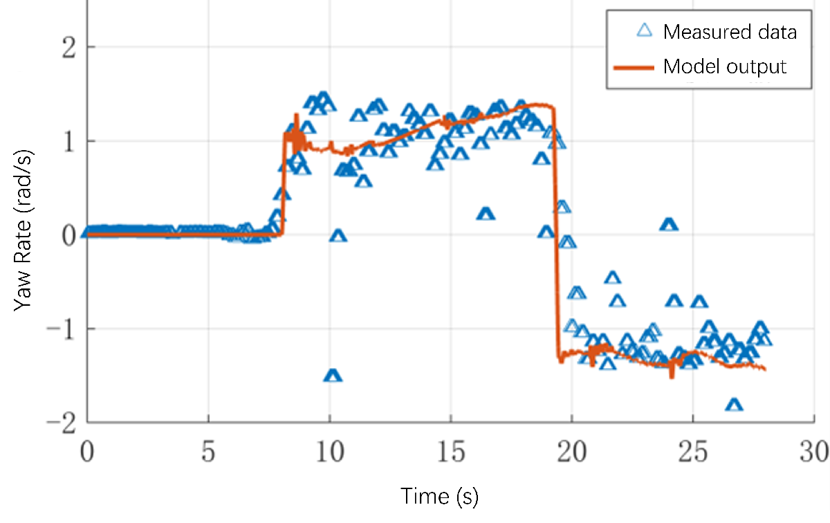
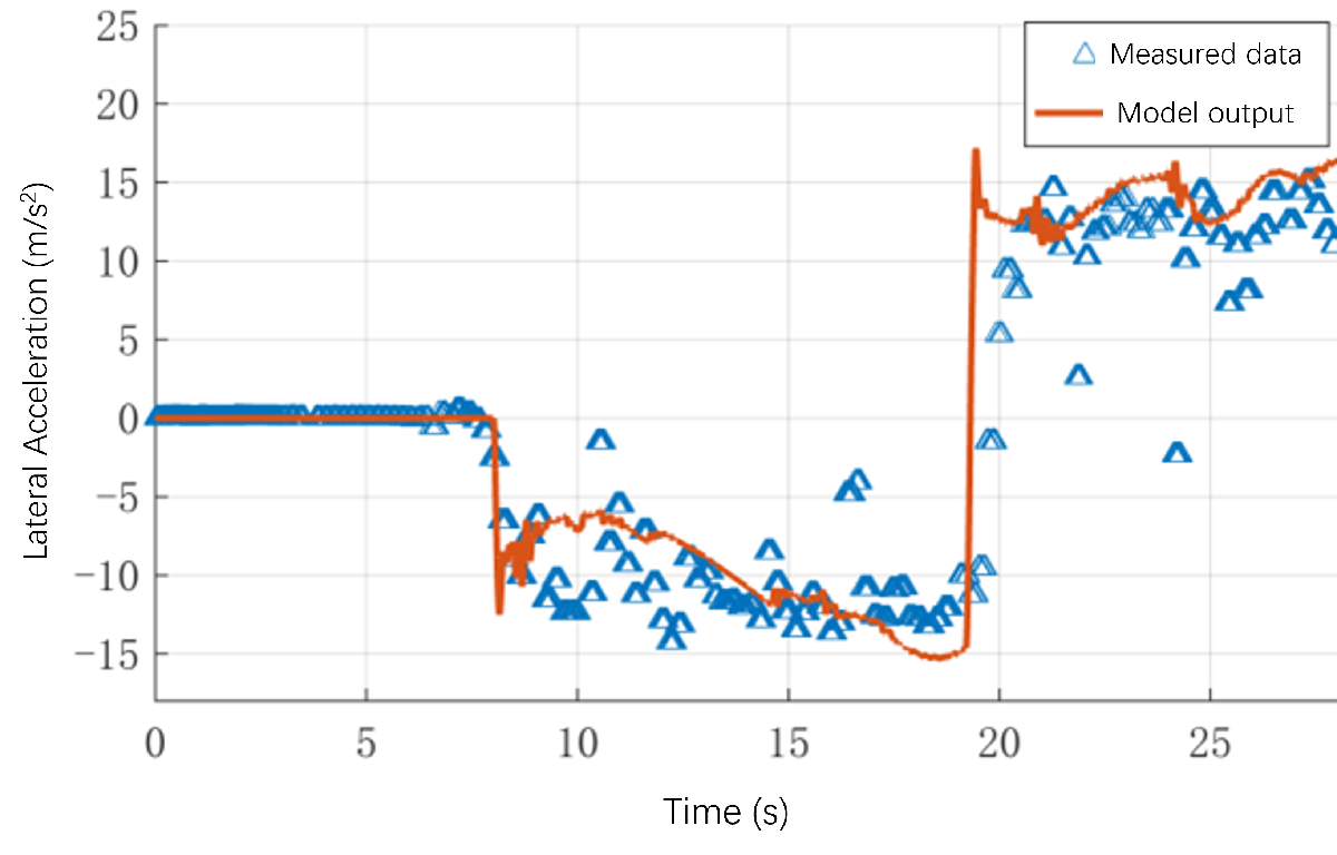
The actual effect of our application based on the vehicle dynamics model is affected by the degree of simulation of the actual vehicle. Then, comparing the data recorded by the racing data acquisition system with the output of the vehicle model under the same working conditions allows us to investigate the similarity between the model and the actual car’s performance. This also helps us to determine the areas for improvement through analysis.
To verify the model, we fed the driver operations collected in the figure-of-eight circle project into the vehicle model and then compared the actual vehicle data with the simulation results of the vehicle model. As it can be seen from the figures below, we were able to achieve realistic results through our simulation model. Although only qualitative analysis was performed, it greatly enhanced our confidence in the work done based on the vehicle model.

Closure
So, this was a brief share from our end on how we customized our vehicle model. We believe, using reference applications you can customize the reference models by using your own data or by replacing a subsystem with your own model. This greatly reduces the vehicle development cycle.
We hope you enjoyed reading the blog. To learn more, please check out the reference applications present in the Vehicle Dynamics Blockset and Powertrain Blockset.
- Category:
- Automotive


Comments
To leave a comment, please click here to sign in to your MathWorks Account or create a new one.