Steve on Image Processing

August 17th, 2006

Spatial transformations: Three-dimensional rotation

Blog reader Stephen N., who's been following my posts about spatial transformations, asked me last week how to rotate a three-dimensional image.

The Image Processing Toolbox function tformarray is a very general multidimensional spatial transformer and can be used for three-dimensional rotation. Here's how.

Contents

Make a three-dimensional blob

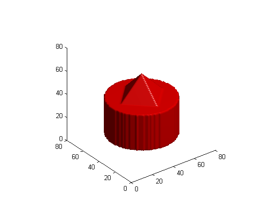
First, let's make a three-dimensional image containing a blob that will easily show the effect of a rotation.

[x,y,z] = ndgrid(-1:.025:1);
blob = z <= 0 & z >= -0.75 & x.^2 + y.^2 <= sqrt(0.25);
blob = blob | (z > 0 & (abs(x) + abs(y) <= (0.5 - z)));

Display the blob using isosurface and patch.

p = patch(isosurface(blob,0.5));
set(p, 'FaceColor', 'red', 'EdgeColor', 'none');
daspect([1 1 1]);
view(3)
camlight
lighting gouraud

Make a 3-D affine tform struct

We want to rotate the blob about its own center. For me, the simplest way to construct an affine transform matrix that will do that is to use three steps:

1. Translate the middle of the blob to the origin.

2. Rotate the blob.

3. Translate the rotated blob back to its starting location.

Here's the first translation:

blob_center = (size(blob) + 1) / 2
blob_center =

    41    41    41

T1 = [1 0 0 0
    0 1 0 0
    0 0 1 0
    -blob_center 1]
T1 =

     1     0     0     0
     0     1     0     0
     0     0     1     0
   -41   -41   -41     1

Now here's the rotation. In this example we'll rotate about the second dimension.

theta = pi/8;
T2 = [cos(theta)  0      -sin(theta)   0
    0             1              0     0
    sin(theta)    0       cos(theta)   0
    0             0              0     1]
T2 =

    0.9239         0   -0.3827         0
         0    1.0000         0         0
    0.3827         0    0.9239         0
         0         0         0    1.0000

And here's the final translation.

T3 = [1 0 0 0
    0 1 0 0
    0 0 1 0
    blob_center 1]
T3 =

     1     0     0     0
     0     1     0     0
     0     0     1     0
    41    41    41     1

The forward mapping is the composition of T1, T2, and T3.

T = T1 * T2 * T3
T =

    0.9239         0   -0.3827         0
         0    1.0000         0         0
    0.3827         0    0.9239         0
  -12.5691         0   18.8110    1.0000

tform = maketform('affine', T);

Let's do a quick sanity check: the tform struct should map the blob center to itself.

tformfwd(blob_center, tform)
ans =

    41    41    41

What the tformarray inputs mean

Now let's see how to make the inputs to the tformarray function. The syntax of tformarray is B = tformarray(A, T, R, TDIMS_A, TDIMS_B, TSIZE_B, TMAP_B, F).

A is the input array, and T is the tform struct.

R is a resampler struct produced by the makeresampler function. You tell makeresampler the type of interpolation you want, as well as how to handle array boundaries.

R = makeresampler('linear', 'fill');

TDIMS_A specifies how the dimensions of the input array correspond to the dimensions of the spatial transformation represented by the tform struct. Here I'll use the simplest form, in which each spatial transformation dimension corresponds to the same input array dimension. (Don't worry about the details here. One of these days I'll write a blog posting showing an example of when you might want to do something different with this dimension mapping.)

TDIMS_A = [1 2 3];

TDIMS_B specifies how the dimensions of the output array correspond to the dimensions of the spatial transformation.

TDIMS_B = [1 2 3];

TSIZE_B is the size of the output array.

TSIZE_B = size(blob);

TMAP_B is unused when you have a tform struct. Just specify it to be empty.

TMAP_B = [];

F specifies the values to use outside the boundaries of the input array.

F = 0;

Call tformarray to transform the blob

blob2 = tformarray(blob, tform, R, TDIMS_A, TDIMS_B, TSIZE_B, TMAP_B, F);

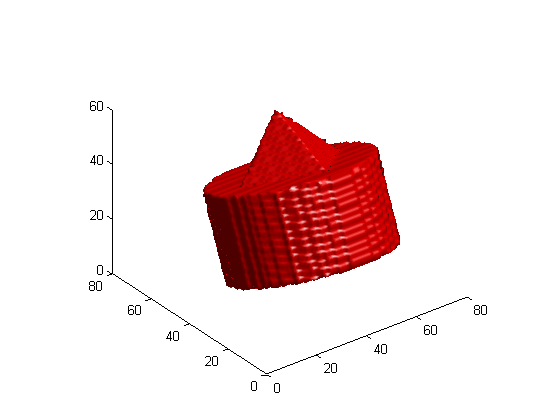
Display the rotated blob

clf
p = patch(isosurface(blob2,0.5));
set(p, 'FaceColor', 'red', 'EdgeColor', 'none');
daspect([1 1 1]);
view(3)
camlight
lighting gouraud


Get the MATLAB code

Published with MATLAB® 7.2

33 Responses to “Spatial transformations: Three-dimensional rotation”

  1. Stephen N. replied on :

    The makeresampler function allows only ‘nearest’, ‘linear’, ‘cubic’ as an interpolant method. Is there an easy way to
    implement ’spline’ interpolation? How does that work?

  2. Steve replied on :

    Stephen - no, makeresampler does not support spline.

  3. Stephan Nickell replied on :

    But the resampling ‘Type’ can be ‘custom’. And here a ‘ResampleFcn’ can be defined wich can be a spline function, right? Do you have an example for that?

  4. Steve replied on :

    No, spline interpolation is a different beast. It isn’t just a matter of using a different interpolation kernel.

  5. majdi chakroun replied on :

    i want a program that let me to convert from several 2D slices to 3D image
    can you help me please
    thank you

  6. Steve replied on :

    Majdi - Take a look at this contribution on the MATLAB Central File Exchange.

  7. Dan replied on :

    hey I have a 3D control grid, I know the coordinates of my original control grid points and the new control grid points. I just want tformarray to deform my 3D image according to my deformed control grid but i can’t get the syntax correctly. What’s the correct way to input this data? I’m trying to use TMAP_B for this purpose. it keeps giving me errors about my dimensions not matching.
    Ax = list of new points x coordinate
    Ay = etc. for y.
    Az…
    .
    .
    Bz = list of old points z coordinate
    I’m inputing TMAP_B as [Ay Ax Az By Bx Bz];

    and my control grid resolution does not match my image resolution.

    thanks

  8. Steve replied on :

    Dan—If your control grid resolution does not match your image resolution, then it sounds like you want to infer a three-dimensional transformation from your control points and then apply that transformation to your image. tformarray doesn’t do that. In fact, there isn’t a function in the Image Processing Toolbox that infers 3-D transformations. The TMAP_B can be used when you know exactly which input-space location corresponds to every output-space location. For an example that shows how to use TMAP_B in this fashion, see my function iminterpn.

  9. Dan replied on :

    I looked at the iminterpn function but I’m not entirely sure how to get it to do what I want.

    I have a routine that can calculate the transformation by determining where each individual pixel is moved because of the control grid. The problem is that the pixels are moved by non-integer amounts and when you expand a object the spaces in between the pixels aren’t filled by this method.

    tformarray only appears to work as interpolator from what I’ve seen. Can I use it to reconstruct the image if I can tell it where each individual pixel is moved to? Ie. fill in the space between sparse pixels and stay true to the original image?

  10. Steve replied on :

    Dan—The problem you describe with pixels not being filled in by your method is characteristic of forward mapping spatial transformation algorithms. Inverse mapping algorithms do not have this problem. See my April 2006 and May 2006 posts for more information. tformarray and imtransform use inverse mapping. If I understand your description correctly, then yes, I think tformarray can do what you want.

  11. Koen replied on :

    Hi Steve,

    I had a lot of help from your blogs, and they got a lot of my problems solved. However there remains one obstacle: I am trying to rotate an entire CT-image set (512×512x100). Using the tformarray this should be simple, following the example, and for rotation on the axial plane this works fine. In the Y-plane however, there is the problem that the Z-direction is sampled differently than the X and Y. I tried scaling/rescaling in the translation matrices but this did not work. Do you have any ideas? Probably this can be dealt with using the input arguments of tformarray?

  12. Steve replied on :

    Koen—Unlike imtransform, tformarray does not offer syntaxes to scale any of the axes. You will have to create an affine scaling matrix yourself, and then compose it (via matrix multiplication) with your affine rotation matrix.

  13. Daniel W. replied on :

    Steve can you take a look at this piece of code which I programmed based on your example.

    Why are the results in fig 3 and 4 not the same?

    ——–

    close all
    clear all
    
    dims = 17;
    
    cube = zeros([dims dims dims]);
    
    [x,y] = meshgrid(-floor(dims/2):floor(dims/2),-floor(dims/2):floor(dims/2));
    cube(:,ceil(dims/2),:) = sqrt(x.^2+y.^2) < dims/2;
    
    figure(1);
    p = patch(isosurface(cube,0.5));
    set(p, 'FaceColor', 'red', 'EdgeColor', 'none');
    daspect([1 1 1]);
    view(3)
    camlight
    lighting gouraud
    
    phi = pi/2;
    
    center = ceil(dims/2);
    
    P1 = [1 0 0 -center; 0 1 0 -center; 0 0 1 -center; 0 0 0 1]';
    P2 = [1 0 0 center; 0 1 0 center; 0 0 1 center; 0 0 0 1]';
    R = [cos(phi) 0 -sin(phi) 0; 0 1 0 0; sin(phi) 0 cos(phi) 0;0 0 0 1]';
    
    T = maketform('affine',P1*R*P2);
    S = makeresampler('linear', 'fill');
    
    %% check transform
    
    index = find(cube);
    [y , x, z] = ind2sub(size(cube),index);
    
    figure(2);
    scatter3(x,y,z);
    view(3)
    
    tesp = tformfwd(T,[x y z]);
    figure(3);
    scatter3(tesp(:,1),tesp(:,2),tesp(:,3));
    view(3)
    
    %% apply transform to cube and show results
    
    cubeR = tformarray(cube,T,S,[1 2 3],[1 2 3],size(cube),[],0);
    
    figure(4);
    p = patch(isosurface(cubeR,0.5));
    set(p, 'FaceColor', 'red', 'EdgeColor', 'none');
    daspect([1 1 1]);
    view(3)
    camlight
    lighting gouraud
    
  14. Steve replied on :

    Daniel—Because you’ve reversed the dimension order in the output of ind2sub, compared to the dimension order you’re passing to tformfwd and tformarray. In your call to tformarray, you are mapping the first, second, and third dimensions of the mathematical transformation to the first, second, and third dimensions of the input and output arrays. Try this instead:

    cubeR = tformarray(cube,T,S,[2 1 3],[2 1 3],size(cube),[],0);
    
  15. Jen replied on :

    New to 3D graphics:
    How should one specify a 3D volume for transformation functions such as tformarray when starting with a m by n matrix where m is the number of points, n1 corresponds to x, n2 to y and n3 to z? Thanks

  16. Steve replied on :

    Jen—I don’t understand your question. Can you be more specific?

  17. Jen replied on :

    Sorry. If we have a matrix specifying 3D coordinates:

    point dimension
    x y z
    1 x1 y1 z1
    2 x2 y2 z2

    m
    and we want to transform it, how should we input this 3D volume appropriately for tformarray?

  18. Steve replied on :

    Jen—To transform points, you want tformfwd, not tformarray.

  19. Daniel W. replied on :

    Thanks a lot Steve for your reply!
    It is true, I am still getting sometimes confused with matlab indexing, i.e. (y,x,z) instead of (x,y,z) ;)

  20. Shalin Mehta replied on :

    Hi Steve,

    How can one inform tformarray about the range of output space co-ordinates? I need to translate a 3D stack in XY plane but want the output space range to be the same as input range. Currently, I have used ‘XData’, ‘YData’ options with imtransform and am applying it to each slice in sequence.

    thanks.

  21. Steve replied on :

    Shalin—tformarray is a low-level function that works only in the natural MATLAB array indexing coordinates. You can control the output size with the TSIZE_B parameter, but you’ll need to fold any spatial coordinate system scaling into the definition of the transformation.

  22. Rui replied on :

    Hi Mr. Steve,

    I’m doing research in iris biometric images.

    I’m trying to rotate a 2D image in yaw, pitch and roll, i.e. in a range of 30º. It only works fine with yaw (with the pitch and roll set to 0º).

    For pitch and roll, I only can get good visual results in the range:
    1 < (pitch, roll) < -1

    I = imread('something');
    
    Y=-10;
    P=0.02;
    R = 0;
    
    yawMatrix = [cosd(Y) -sind(Y) 0; sind(Y) cosd(Y) 0; 0 0 1];
    pitchMatrix = [cosd(P) 0 sind(P); 0 1 0; -sind(P) 0 cosd(P)];
    rollMatrix = [1 0 0; 0 cosd(R) -sind(R); 0 sind(R) cosd(R)];
    
    T = yawMatrix * pitchMatrix * rollMatrix;
    
    t_proj = maketform('projective',T);
    I_projective = imtransform(I,t_proj, 'size', size(I), 'fill', 128);
    
    imshow(I_projective);
    

    Thanks in advance any help.

    Best regards

  23. Steve replied on :

    Rui—Two thoughts come to mind that might help you with debugging your code. First, make sure that your T matrix is not tranposed from what maketform expects. Review the reference page for maketform to be sure. Second, if the image doesn’t look like what you expect, the problem could be with your spatial transformation. Use tforminv to transform points from output space back to input space and make sure the spatial warping function is what you expect it to be.

  24. Jan replied on :

    Hi Steve

    Very useful code, yet what if I parts of my rotated+translated object are outside the original boundaries? How can I define the boundaries as such that the output object (suggest I want to rotate a long cylinder for 45 degrees and obviously, one of the dimensions is becoming larger but standard tformarray is going to cut that part, no?) is incorporated entirely in the new volume? I can find the expected outbounds of the volume (findbounds), but how feeding them to tformarray? I tried to pad the 3D array with zeros (depending on the outcome of findbounds), but I think I am doing things wrong … Because when I pad the matrix, my center position changes and as such my tform changes too …

    Thanks in advance

    Jan.

  25. Steve replied on :

    Jan—The function tformarray does not have the convenience syntaxes of imtransform for setting up alternative coordinate system mappings. Any coordinate system scaling or translating that you might need, for example to shift the image over in order to capture all of it, have to be incorporated into the spatial transformation function itself.

  26. Jan replied on :

    Thanks for the answer, Steve. I thought I had some kind of a solution by estimating the bounds using the function

    findbounds

    . By pre- or postpadding of the 3D array, recalculating the

    TFORM

    structure (based on a new translation due to padding) I tried to fit the entire volume. Yet sometimes this does not work (strangely enough in the Z-direction). Part of my volume is still out of bound. Is this due to the approximation of the findbounds algorithm? Or am I doing something wrong?

    Thanks

    Jan.

  27. Steve replied on :

    Jan—What kind of tform are you using? Does it have a forward mapping? You can find out by trying to use tformfwd. If your tform does not have a forward mapping, then it’s much harder for findbounds to figure out where the transformed image is going to “land” in output space; it has to use a search method.

  28. Mark replied on :

    Hi Steve,

    Using tformarray, I am able to reformat axial slices of my CT data to obtain coronal and sagittal views. However, I would like to reformat my axial slices along an oblique axis (say 15 degrees from the horizontal) to simulate gantry tilt. How can I do this?

    Thanks

  29. Steve replied on :

    Mark—I don’t know anything about that, but it sounds like something that could be implemented using a 3-D affine transform.

  30. Imon replied on :

    Hi,

    I am working on trajectory analysis. Let’s say I already have the trajectory corresponding to a car moving on the ground. I can plot the trajectory by plot(x,y). Now I want to create a small JPEG of the car and superimpose it on the trajectory plot to see the position of the car. For this, I need to insert the JPEG multiple number of times onto the (x,y) plot and also rotate it. Imagine a car going round in a circle, and you have to plot its position and orientation say, every 1 second. Can you help?

  31. Steve replied on :

    Imon—Form an affine transformation matrix that rotates and shifts the image appropriately, and then use imtransform to warp the image. Alternatively, just rotate the image using imrotate, display the image superimposed on your plot, and give the image object the appropriate XData and YData properties so that it appears in the desired location.

  32. reji A p replied on :

    hai,
    I have rotated an image through 45 ,then to obtain the original image I rotated through -45.I’m not getting the exact original image.How can I get the original image back?
    reji

  33. Steve replied on :

    Reji—Since rotation involves interpolation, you can’t expect to get the original image back exactly except for angles that are multiples of 90 degrees.

Leave a Reply

Wrap code fragments inside <pre> tags, like this:

<pre class="code">
a = magic(3);
sum(a)
</pre>

If you have a "<" character in your code, either follow it with a space or replace it with "&lt;" (including the semicolon).


Steve Eddins manages the Image & Geospatial development team at The MathWorks and coauthored Digital Image Processing Using MATLAB. He writes here about image processing concepts, algorithm implementations, and MATLAB.

  • Sana: hi steve, could you explain to me how i would be able to use the dir function, to do a loop through a directory...
  • Nishtha: Sir, I have preprocessed the image in following steps: [1] adaptive histogram equalization [2] thresholding...
  • Kristof: I also strongly support the idea. I have just recently bumped into the problem that im2single was not...
  • Steve: David—I’ m glad you found it useful!
  • David Lalejini: I found your example very useful for finding connected nodes in a large set of input pairs. I start...
  • tommy: Dear Steve, I have a question,please if you are kind to help me regarding the accumulator array dimensions of...
  • Steve: Abc—I don’t know how to distinguish the faces. You might try posting your question in the MATLAB...
  • Manju: well if we have a few ovals within each other like in a cell how do we measure the distance from the center...
  • Steve: Manju—What do you mean? How is each region defined?
  • Manju: if we have 2-3 regions within each other how do we measure the regions of each one?

These postings are the author's and don't necessarily represent the opinions of The MathWorks.