Mixing Analog and Digital Signals
Idin's pick this week is Analog/Mixed-Signal Examples by Dick Benson.
Hi, my name is Idin, and this is my first post for Pick of the Week as a guest blogger. My background is in wireless communications,
and that's the area I support as an Applications Engineer at MathWorks. I started using MATLAB occasionally during my undergrad
days, but these days, I have MATLAB open on my desktop all the time. I mostly focus on Simulink and our tools for targeting
wireless communication hardware.
Communication systems (wired or wireless) are typically a complex mix of analog and digital components. Simulink is one of
a small set of simulators that can naturally simulate analog and digital components in the same system. Examples of such systems
include phase-lock-loops (PLL), clock data recovery (CDR), and analog-to-digital converters (ADC). Components that include both digital and analog portions are referred to as "mixed-signal".
This week's pick is a collection of examples created by my colleague, Dick Benson. It is an impressive set of 60+ Simulink
models that include, among others, an interleaved ADC, clock multiplying delay lock loop, clock recovery for NRZ data, PLL,
fractional N PLL, digital fractional N PLL, Sigma-Delta ADC, elliptic LC filter design, RF examples, numerous Circuit Level
examples such as switching power supplies, class D H bridge audio amp, active filters, passive filters, and simulated vector
network analyzers.
What I like about these models is that they typically show how a simple system can be designed and simulated, and then go
on to show how real-world impairments and mitigation algorithms can be modeled. As such, they can be used to learn about both
the Simulink environment, and the theory behind the systems being modeled.
These models also include many reusable blocks that can complement the Simulink libraries for an analog/mixed-signal designer.
Some examples of these blocks are: VCO with user-defined phase noise, analog spectrum analyzer, transfer function estimator,
peak-to-peak jitter measurement, and switched-capacitor circuits.
Let's look at the set of models concerning PLLs.
We can start with the first model, Simple PLL, shown below:
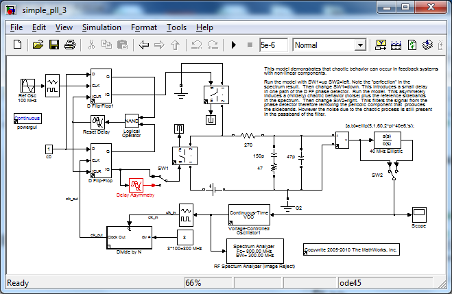 This model shows a simple PLL structure that multiplies the reference 100MHz input frequency by a factor of 8 to produce an
800MHz signal at the output of the VCO. If run as-is, the output spectrum look like the following:
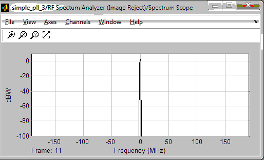 Note the purity of this tone (clear to at least 100dB). This models an ideal system. In a real system, the two D flip-flops
on the top left may not have identical switching characteristics (in fact, they almost certainly won't). To model this behavior,
we switch in the "delay asymmetry" block (block in red). This models a real impairment in the system, and we can see its effect
on the output:
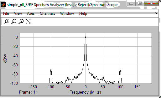 Note the two spurs at 100MHz away from our desired carrier (this is the frequency of the reference input signal).
To mitigate this impairment, we can introduce a low-pass filter on the VCO control voltage (change switch SW2 to the right),
which results in the following output:
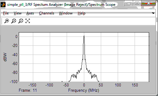 You can see that we have now filtered out the spurs at +/-100MHz. However, we're still allowing some noise close to our desired
carrier. By making the filter more aggressive, we can eliminate more of this noise, but that will negatively affect our loop
bandwidth (which relates to the loop's ability to acquire the initial phase lock, or to recover from losing its lock). This
is the classic engineering trade-off: we desire a larger loop bandwidth, and less noise. A PLL designer can use a model like
this to determine how he/she will make that trade-off.
The next three PLL models in this set show more sophisticated designs, which multiply the reference input frequency by a non-integer
factor (known as fractional-N PLLs). The two models with "digital compensation" highlight Simulink's ability to naturally
integrate digital and analog components, as well as practical techniques for producing a clean tone at the output (see the
models for references).
Overall, the PLL models can be useful whether you're an experienced PLL designer or if you’re just trying to learn about PLLs.
For a beginner these models can serve as a tutorial, and because of the dynamic simulation capability, they can be used to
show how different choices affect the loop's behavior. For a PLL expert, these models show how the Simulink environment lends
itself to simulating PLLs and studying the trade-offs that any designer will have to make. The models also provide a library
of reusable components (especially for measurements) that can be used in any analog/mixed-signal model.
This has been a great submission from Dick Benson who has 25+ years of experience in this field, and I encourage you to look
at his other submissions for more great examples of how Simulink can be used for communication system simulations.
As always, we welcome your comments!
 This model shows a simple PLL structure that multiplies the reference 100MHz input frequency by a factor of 8 to produce an
800MHz signal at the output of the VCO. If run as-is, the output spectrum look like the following:
 Note the purity of this tone (clear to at least 100dB). This models an ideal system. In a real system, the two D flip-flops
on the top left may not have identical switching characteristics (in fact, they almost certainly won't). To model this behavior,
we switch in the "delay asymmetry" block (block in red). This models a real impairment in the system, and we can see its effect
on the output:
 Note the two spurs at 100MHz away from our desired carrier (this is the frequency of the reference input signal).
To mitigate this impairment, we can introduce a low-pass filter on the VCO control voltage (change switch SW2 to the right),
which results in the following output:
 You can see that we have now filtered out the spurs at +/-100MHz. However, we're still allowing some noise close to our desired
carrier. By making the filter more aggressive, we can eliminate more of this noise, but that will negatively affect our loop
bandwidth (which relates to the loop's ability to acquire the initial phase lock, or to recover from losing its lock). This
is the classic engineering trade-off: we desire a larger loop bandwidth, and less noise. A PLL designer can use a model like
this to determine how he/she will make that trade-off.
The next three PLL models in this set show more sophisticated designs, which multiply the reference input frequency by a non-integer
factor (known as fractional-N PLLs). The two models with "digital compensation" highlight Simulink's ability to naturally
integrate digital and analog components, as well as practical techniques for producing a clean tone at the output (see the
models for references).
Overall, the PLL models can be useful whether you're an experienced PLL designer or if you’re just trying to learn about PLLs.
For a beginner these models can serve as a tutorial, and because of the dynamic simulation capability, they can be used to
show how different choices affect the loop's behavior. For a PLL expert, these models show how the Simulink environment lends
itself to simulating PLLs and studying the trade-offs that any designer will have to make. The models also provide a library
of reusable components (especially for measurements) that can be used in any analog/mixed-signal model.
This has been a great submission from Dick Benson who has 25+ years of experience in this field, and I encourage you to look
at his other submissions for more great examples of how Simulink can be used for communication system simulations.
As always, we welcome your comments!
- 类别:
- Picks




评论
要发表评论,请点击 此处 登录到您的 MathWorks 帐户或创建一个新帐户。