Configurable Simulink Model for DC-DC Converters with PWM PI Control
Idin's pick for this week is Configurable Simulink Model for DC-DC Converters with PWM PI Control by Yi Cao.
Dr. Yi Cao has contributed a wealth of useful tools to the File Exchange (I saw 66 at the time of this writing). This week’s
Pick came in handy for me recently as I was trying to investigate and demonstrate the value of Simulink for modeling DC-DC converters .
Power management ICs (PMICs) are critical pieces of most electronic systems, especially battery-operated devices such as mobile phones and tablets. As
it was put to me recently, “PMICs are equivalent to the devices that turn the lights on at power-up, and turn them off when
powering down.” The PMIC provides required amounts of power to different parts of the system. An important part of a PMIC
is typically one or more DC-DC converter to provide regulated voltages to different parts of a system.
In this submission Yi Cao provides a nice example of how the behavior of DC-DC converters can be modeled and simulated in
Simulink. These converters fall under three general classes: buck, boost, and buck-boost (buck steps down the input voltage,
boost steps it up, and buck-boost inverts the polarity). Yi’s example covers all three classes (using their classic topologies).
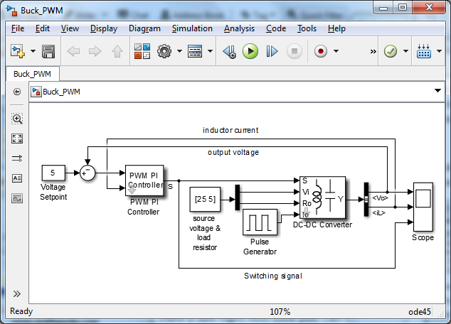
The core of this submission is a Simulink model that shows how the whole system works.
 This model is simulating a full closed-loop system. The converter needs to hold its output voltage constant as the amount
of current being drawn varies. The control loop (and the PWM PI controller) work to correct fluctuations in output voltage
(usually due to fluctuations in output current). He's done some good work to create one customizable block that can be configured
to simulate any desired topology (buck, boost, or buck-boost).
A really nice feature of this submission is the included tutorial (PDF) on deriving the mathematical equations used in the
model from circuit diagrams. I highly recommend reading through this document. And if there was any doubt that the derivations
were correct, my colleague Dick Benson created a circuit-level model of the same system to check the results.
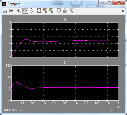
The results from the circuit simulation were nearly identical to those from Yi’s model. The figure below shows two plots:
the output voltage and inductor current. In each plot the result of the circuit simulation is overlaid on top of the output
from Yi’s model. The two traces can hardly be distinguished.
 If you would like to see some examples of these systems simulated using real circuit elements, download the Mixed-Signal Library
from the bottom of this page, and go to the “Switching Power” examples. Note that the examples using circuit elements require Simscape Electrical . As always, your thoughts and comments are greatly appreciated.
 This model is simulating a full closed-loop system. The converter needs to hold its output voltage constant as the amount
of current being drawn varies. The control loop (and the PWM PI controller) work to correct fluctuations in output voltage
(usually due to fluctuations in output current). He's done some good work to create one customizable block that can be configured
to simulate any desired topology (buck, boost, or buck-boost).
A really nice feature of this submission is the included tutorial (PDF) on deriving the mathematical equations used in the
model from circuit diagrams. I highly recommend reading through this document. And if there was any doubt that the derivations
were correct, my colleague Dick Benson created a circuit-level model of the same system to check the results.
The results from the circuit simulation were nearly identical to those from Yi’s model. The figure below shows two plots:
the output voltage and inductor current. In each plot the result of the circuit simulation is overlaid on top of the output
from Yi’s model. The two traces can hardly be distinguished.
 If you would like to see some examples of these systems simulated using real circuit elements, download the Mixed-Signal Library
from the bottom of this page, and go to the “Switching Power” examples. Note that the examples using circuit elements require Simscape Electrical . As always, your thoughts and comments are greatly appreciated.
- カテゴリ:
- Picks


コメント
コメントを残すには、ここ をクリックして MathWorks アカウントにサインインするか新しい MathWorks アカウントを作成します。