
Using Test Points to log Signals for Software-In-The-Loop Simulation
This week's post is a suggestion from Raymond Estrada from MATLAB and Simulink Consulting Services. Raymond reached out recently to share a tip for verifying and validating logged signals in the code generated from Simulink.
The Problem
It's a common practice in the verification and validation world to run simulations and look at the value of outputs and (sometimes) intermediate signals, and compare those to expected values.
When generating code using Simulink Coder and Embedded Coder, you want to verify that those values are the same (within tolerance) as what you got in simulation. That’s what we call “equivalence testing” or “back-to-back testing”, where you compare the results from normal mode simulation to results from Software-in-the-Loop Simulation (SIL) and Processor-in-the-Loop Simulation (PIL).
Now here is where you can run into a problem: Some of those values you need to observe don’t exist in the generated code. Intermediate signals may not be available in generated code due various optimizations like Signal storage reuse and Eliminate superfluous local variables (Expression folding). Expression folding is an optimization that collapses block computations into single expressions in generated code.
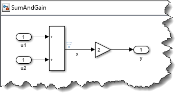
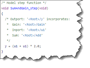
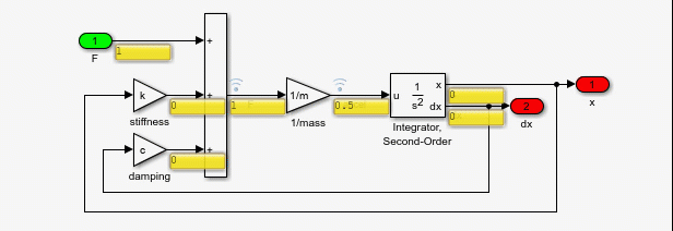
To illustrate this, let's use a very simple model where I add two signals and multiply the result by 2. I want to verify the results for the logged signal "x".
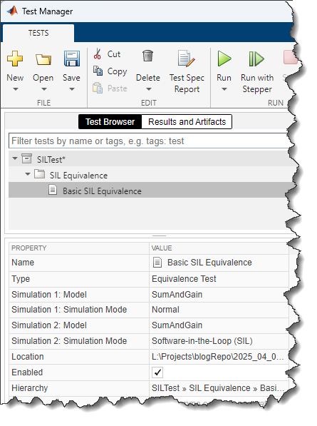
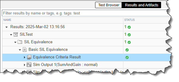
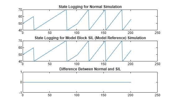
Using the Simulink Test Manager we can create an Equivalence Test. This test simulates the model in normal mode and Software-in-the-Loop Simulation, and compare the results.
We run the test and see that if failed. When expanding the test results, we can see that the logged signal x is not present in the SIL results.
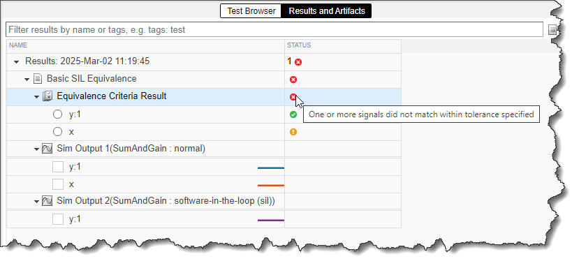
When hovering over the equivalence criteria result, we see this note:
One or more signals did not match within tolerance specified
Let's see how to debug and fix this.
The Explanation
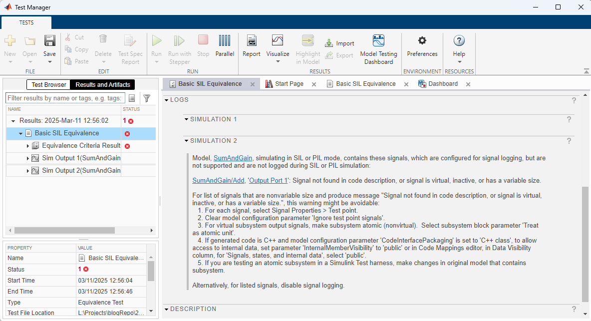
In the Test Manager, if you look carefully at the logs sections of the test results, you will find more explanations:
Let's also run the test programmatically to make the log easier to search and copy. For that, I like to use the function matlab.unittest.TestSuite.fromProject. This function conveniently finds all the tests in a project and creates a test suite.
suite = matlab.unittest.TestSuite.fromProject(currentProject);
results = run(suite);
What this log tells us is that the generated code does not contain a variable corresponding to the logged signal x.
When looking at the generated model step function, we can confirm that expression folding has been applied, combining the Sum and Gain blocks in a single expression:
The Solution
Let's apply the first suggestion in the above log:
1. For each signal, select Signal Properties > Test point.
If you are not familiar with test points, I recommend this documentation: Configure Signals as Test Points.
In this case, a simple way to add the test point is using the Property Inspector:

With this change, we can run the test suite again to confirm that the test point fixes the issue and enables the test to pass.
Conclusion & Considerations
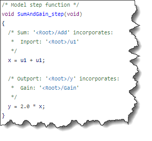
Adding a Test Point is one solution that allows for verification of requirements using signals that would otherwise be optimized via expression folding. However, note that the addition of a test point did change the generated code. In this case, the model step function becomes:
Since adding test points changes the code and can block optimizations, you only want to use this where it is truly necessary. Also, since they impact the generated code, test points should persist throughout the design and should not be toggled between the different stages of development (development, testing & verification, code generation).
Now it's your turn
Are you verifying and validating signals internal to your algorithms? Let us know in the comments below if you have tips and tricks for that.


コメント
コメントを残すには、ここ をクリックして MathWorks アカウントにサインインするか新しい MathWorks アカウントを作成します。