
Stateflow sliding mode controller demo
Will‘s pick this week is Stateflow sliding mode controller demo by Bogumila & Zbigniew Mrozek.
I always enjoy a good controls problem modeled with Simulink and Stateflow. Dr. Mrozek’s submission provides a simulation of a “platform mobile carrying robot with welding equipment.” They model the dynamics of the robot as a linear time-invariant system. You can see it represented by the block labeled as “LTI System” in the Simulink model.
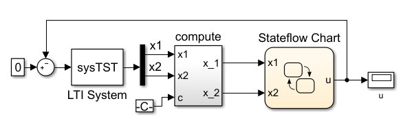
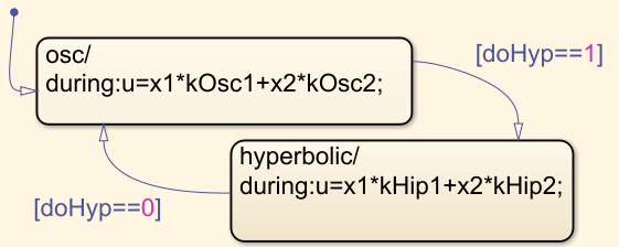
To the right is a block labeled “Stateflow Chart.” This is the controller that supplies an input to the robot. If we open up the details of the chart, we observe that there are two control modes: oscillatory and hyperbolic. Both are proportional controls, but they rely on different gain constants (those variables that start with “k” in the u equation).
The submission includes a MATLAB script that defines various parameters used by the simulation. The script then executes the simulation for different initial conditions of the robot and different control modes. Effectively, we study what happens when the robot is given a particular initial velocity and initial displacement from the resting position.
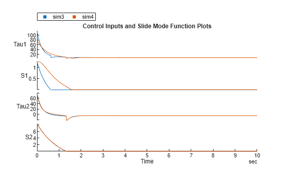
The end result is a rather satisfying figure that displays the position of the robot on the x axis and velocity on the y axis. Each point on a given line corresponds to the position and velocity of the robot at a particular moment in the simulation. The green trajectories are hyperbolic and quickly go unstable. The blue trajectories are oscillatory unstable simulations that rotate and move away from the origin of the coordinate system. The red trajectories are from sliding mode runs, a control strategy that offers “fast response and short settling time.”

Wonderful though this is, there’s always room for improvement. Here are a few ideas I have that would make the exercise easier for the developer and end-user.
- While the textbook associated with this submission may have an explanation, the script itself provides little insight into the derivation of the linear time-invariant system. A Live Editor script could be used to document the methodology.
- Better yet, why jump straight into an LTI system when you have Simscape Multibody? You could model the robot and its platform much more clearly and accurately this way. You could then rely on Simulink Control Design to linearize the plant model about any operating point.
- The Stateflow chart is somewhat unnecessary in this model. So far as I can tell, the controller remains in one of the two modes for the duration of the sim. A simple Switch block or some modification of the run script could be used instead.
- Simulink Dashboard blocks would help make the model more interactive for anyone interested in trying different test cases without resorting to the script.
- And finally, the script itself would be greatly simplified if it leveraged SimulationInput objects.
Let us know what you think here or leave a comment for Bogumila & Zbigniew.
- 类别:
- Picks


评论
要发表评论,请点击 此处 登录到您的 MathWorks 帐户或创建一个新帐户。