
STORX: Exploring Shape and Topology Optimization
George's pick this week is STORX by Amir Mirzendehdel (University of Kansas) and Krishnan Suresh (UW-Madison).
Say you've got some space to fill with material, a few places where the part is bolted down, and some forces pushing on it. You want a shape that's strong and stiff without wasting material, a shelf bracket that won't sag but isn't a solid lump of steel. Finding that shape by hand is hard, so you let your computer do it: simulate how a design holds up, see where the material is loafing, nudge the shape, and repeat a hundred times or so. The simulation half is finite element analysis; the nudging half is optimization. STORX bundles both, along with many years' worth of methods for doing the "nudging".
I really like how the methods span the full range of design freedom: size (tune a few thicknesses), shape (slide the boundaries around), and topology (let the algorithm decide where material should exist at all, punching holes and growing the branching, almost skeletal structures that no one would draw by hand). Those organic black shapes in the paper's figures are what topology optimization produces when it asks the simulation "does every bit of material earn its keep?"
In their paper, the authors call their design principle "separation of intent". The physics solver sits behind an abstract interface, so you can swap what you're simulating without touching the optimizer:
fea2d_elasticity
fea2d_thermal
fea2d_thermoelasticity
fea2d_fluid
This pattern is fairly consistent across the toolbox: new objectives and manufacturing rules are added as derived classes behind shared interfaces, which gives the codebase clear extension points.I also like that setting up a run reads about as cleanly as you'd hope:
brep = 'CantileverBeam.brep';
solver = fea2d_elasticity(brep, numElements, material, vectorize);
solver = solver.fixEdge(5);
solver = solver.applyYForceOnEdge(2, -1e5);
objective = densityComplianceElasticity(solver);
constraints = {volume(solver, 0.5)};
mfgConstraints = {minimumFeatureSize_dist(solver, 1.5)};
topopt = density2d_elasticity(solver, objective, constraints, mfgConstraints, 'OC');
topopt = topopt.optimize();
As a non-expert, I appreciate that several key finite-element and sensitivity routines include both vectorized implementations for speed and clearer loop-based versions for learning or debugging, so you can inspect the logic when needed and use the faster path for larger runs.
It also reaches further than a teaching code usually does: general (non-boxy) domains, multiple load cases, self-weight, heat problems, stress and fluid objectives, and a path that ends in actual 3D-printed parts. It's also been used in several student projects on antenna design, wing fluid-structure interaction, and auxetic metamaterials.
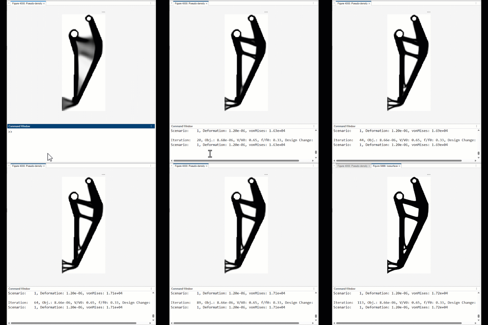
The gif below is generated from running the gripper example (/examples/density_gripper.m)
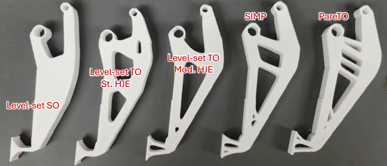
You can also export the optimized designs to STL and 3D-print them. The authors demonstrate exactly that in their paper, printing a gripper optimized in five different ways.





댓글
댓글을 남기려면 링크 를 클릭하여 MathWorks 계정에 로그인하거나 계정을 새로 만드십시오.