Thermal Effects in Electrical Models
Greg's pick this week is Loss Calculation in a Buck Converter Using SimPowerSystems and Simscape by Pierre Giroux
There are several reasons that lead me to choose this submission. It:
- demonstrates the ability to mix modeling different physical domains in the Simulink environment;
- is a good reference for users who are looking to do some efficiency studies on switching power supplies; and
- is a well laid out model with supporting documentation.
Contents
Heat, Please Disperse. There is Nothing to See Here!
Much of the time I spend in the field with our customers focuses on industrial automation applications. In general this means managing electrical power conversion and distribution, as well as controlling motors. In order to apply digital control to these types of applications you normally have to use some sort of power electronics like a MOSFET or IGBT to apply the output from the digital control hardware to the system circuitry.
For power conversion, heat is an important concern. Any heat generated by an electrical system represents an electrical power loss, and for electrical power converters, a reduction in efficiency. In addition, heat that gets generated must be managed to prevent to degradation of the power electronics or surrounding components.
What Can You Investigate with Switching Models that Include Thermal Effects?
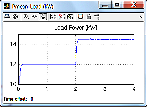
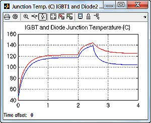
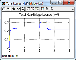
Pierre provides a couple of possible scenarios. He varies both the electrical load, and the frequency at which the power electronic gates are opened and closed.
The increase in electrical load at 2 seconds results in a higher power output from the amplifier.

This leads to an increase in temperature of the power electronic devices, and an increase in operating losses.
Reducing the switching frequency from 10 kHz to 2.5 kHz at 2.5 seconds permits more time for the power electronic devices to dissipate heat, and so the device temperature drops and operating losses recover nicely.


How Does Pierre Include Thermal Effects?
Pierre leverages the capability to mix different physical modeling domains in the Simulink environment, as well as the capability to inject his desired equations for computing losses into the simulation.
| Electrical Model |  |
| __________________________________________________________________________ | |
| Thermal Management Model |  |
| __________________________________________________________________________ | |
| Thermal Model |  |
| __________________________________________________________________________ | |
The electrical modeling is done using Simscape Electrical. The management of the generated heat leverages the basic libraries in Simscape. Pierre uses the various measurement outputs of the IGBT models to compute the amount of heat to inject into the thermal management model using linear state-space blocks from the Simulink library.
Should You Always Include Thermal Effects in Electrical Models?
In short the answer is “no!” In many cases it is not necessary. An electrical model that includes thermal effects could be used to identify appropriate switching frequencies for the power electronics and controller, or general loading capacities of the power amplifier. You can then use this information for controller design or including more dynamic loading of the power amplifier.
In general you want to use the simplest model you can for a particular design purpose. Higher fidelity models are great for determining operating limits, but can bog down simulation speed for system simulations.
Comments
If you would like to leave any comments regarding this post, please click here.
- Category:
- Picks


Comments
To leave a comment, please click here to sign in to your MathWorks Account or create a new one.