
Customizing the Code Generated from Simulink
I want to start by giving you a heads up that guest blogger Erin McGarrity will be coming back soon with more posts about Simulink Coder and Embedded Coder. Before going deeper into code generation topics, I thought it would be a good idea to re-visit the basics of customizing the code generated from Simulink models using Embedded Coder.
It has been almost 10 years since the last time I wrote a basic introduction to code generation on this blog. As you can imagine, things have changed a lot since then, so this week I am sharing the 2023 version of a basic introduction to Embedded Coder.
Default Behavior
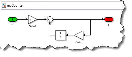
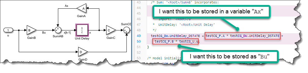
Let's take this simple example model and generate code for it using Embedded Coder
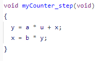
By default, the "step" function for this model looks like this:
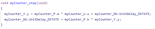
While this code is valid, there are multiple reasons for wanting to customize it.
For this example, I will make the generated code look more like what a human would write, using simple variables like u and y instead of grouping them in the structure modelname_Y.
Customizing Code using Simulink.Parameter and Simulink.Signal Objects
If I don't want the variables being stored in those modelname_Y, modelname_P and modelname_DW structures, the "classic" approach is to define Simulink.Signal and Simulink.Parameter objects for the different modeling elements and specify a different storage class:
% Input signal
u = Simulink.Signal;
u.CoderInfo.StorageClass = 'ExportedGlobal';
% Output Signal
y = Simulink.Signal;
y.CoderInfo.StorageClass = 'ExportedGlobal';
% Unit Delay State
x = Simulink.Signal;
x.CoderInfo.StorageClass = 'ExportedGlobal';
%Gain A
a = Simulink.Parameter;
a.CoderInfo.StorageClass = 'ExportedGlobal';
a.Value = 0.1;
%Gain B
b = Simulink.Parameter;
b.CoderInfo.StorageClass = 'ExportedGlobal';
b.Value = 0.9;
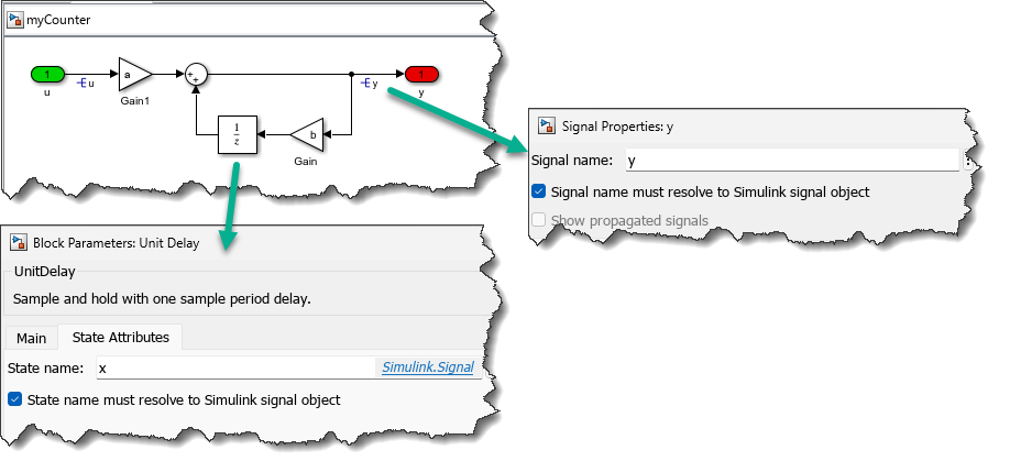
In the model, I associate those objects with signals and block properties:
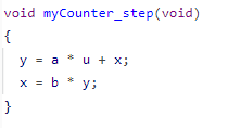
And the generated code now looks like this:
Customizing Code using Code Mapping
A few years ago, we introduced the Code Mapping panel to give you a central location where you can configure how the different modeling elements in a Simulink model map to C code.
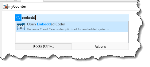
To get started, you first launch the Embedded Coder App. This can be done from the Apps Gallery in the Simulink toolstrip, or using the keyboard shortcut Ctrl+Shift+C. As I described in a previous post, my favorite way to launch this kind of app is hitting Ctrl+. to launch the Actions search and type what I need:
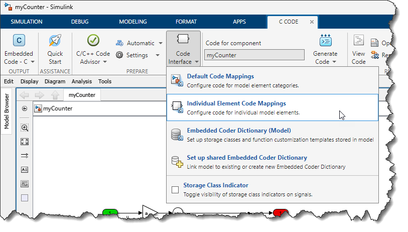
In the C Code tab, the Code Interface dropdown contains the Code Mapping related entries:
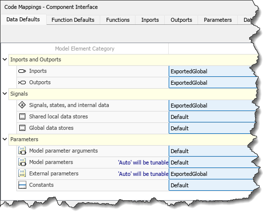
The first thing I can try is changing the default storage class and see if I can get what I want. I set the Inports, Outports, States and External Parameters default storage class to ExportedGlobal:
and now the code I get is:

The data is not stored in structures anymore and the parameters are showing up as a and b, but I still need to do an additional step for the signals and states.
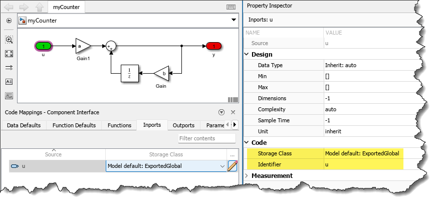
Code Mapping works well teamed up with the Property Inspector. For Inputs, Outputs, Signals and States, Property Inspector allows me to specify the identifier I want.
Once the identifiers have been specified for ports and states, I can generate code and confirm that it behaves as I expect:
Note that those two techniques (parameter/signal objects and Code Mapping) are not mutually exclusive. It is possible to specify code generation properties using signal and parameter objects on top of Code Mapping. This is useful if you want a finer granularity in your specification and/or if you prefer to keep those specifications outside of the model file.
Now it's your turn
After reading this basic introduction, which other code generation topics would you like to see in future posts? Let us know in the comments below.
- カテゴリ:
- Code Generation


コメント
コメントを残すには、ここ をクリックして MathWorks アカウントにサインインするか新しい MathWorks アカウントを作成します。