Loren on the Art of MATLAB

December 16th, 2009

Carving a Dinosaur

Today I’d like to introduce a guest blogger, Ben, who is consultant over in The MathWorks UK. Some of you may have come across his customer projects and demos on image processing. He’s going to talk about one of those demos here.

Contents

Demo Description

This is a demo of reconstructing a 3D shape from multiple images using a simple space-carving approach. This technique is usually used when you need a 3D model of a small artefact which can be placed on a turntable, allowing dozens, even hundreds of images to be captured from around the object. It has been used pretty successfully by museums and the like to create online virtual galleries.

Note: This demo requires the Image Processing Toolbox.

Introduction

A little while ago (is it really four years?!) I was asked to prepare a demonstration for a customer visit. The customer had some samples that they wanted to photograph in order to estimate the volume occupied before and after a chemical process. These samples were smooth but irregularly shaped such that a simple "volume of revolution" calculation was inaccurate. They wanted to know if accurate volume estimation from images was possible, and if so how you might do it.

The demo I produced is enumerated below and is the most basic form of a technique called "space carving" or "shape from silhouettes", where each image is just used as a mask. A lump of voxel "clay" is placed in the middle of the scene and from each image we simply look and see what is outside the object silhouette. Anything outside is carved away. Obviously, this requires us to know where the camera was relative to the object when the picture was taken, which is a whole separate problem.

This technique has been refined over the last decade and can be done in some computationally and memory efficient ways. My approach is neither of these - I went for simplicity over efficiency since my only aim was to explain the technique and show it in MATLAB.

Acknowledgements

The dinosaur images used here were provided by Wolfgang Niem at the University of Hannover.

The camera data used in this example was provided by Dr A. W. Fitzgibbon and Prof A. Zisserman from the University of Oxford Robotics Research Group.

The images and camera data can both be downloaded from the Visual Geometry Group web-pages at the University of Oxford Robotics Research Group.

Setup

All functions for this demo are in the "spacecarving" package and the data in the "DinosaurData" folder.

import spacecarving.*;
datadir = fullfile( fileparts( mfilename( 'fullpath' ) ), 'DinosaurData' );
close all;

Load the Camera and Image Data

This reads the "Dinosaur" directory, loading the camera definitions (internal and external calibration) and image file for each camera. These calibrations have previously been determined from the images using an automatic process that we won't worry about here.

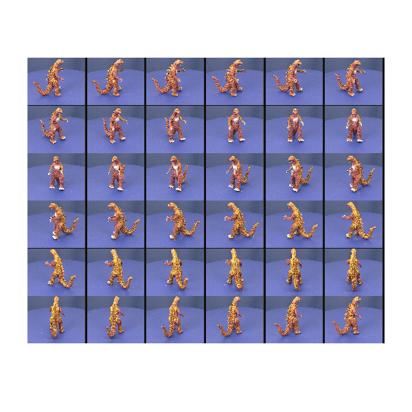
cameras = loadcameradata( datadir )

montage( cat( 4, cameras.Image ) );
set( gcf(), 'Position', [100 100 600 600] )
axis off;
cameras = 
1x36 struct array with fields:
    Image
    P
    K
    R
    T
    Silhouette
    rawP
Warning: Image is too big to fit on screen; displaying at 25% 

Convert the Images into Silhouettes

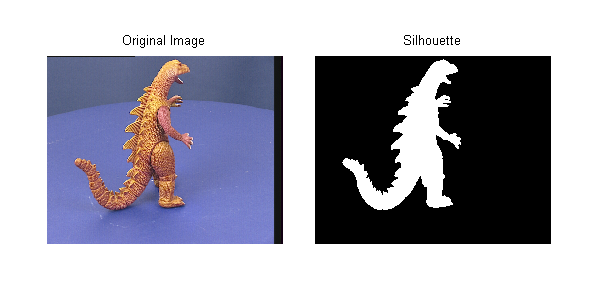
The image in each camera is converted to a binary image using the blue-screen background and some morphological operators to clean up the edges. This becomes the "mask" referred to above. Holes in this mask are particularly dangerous as they will cause voxels to be carved away that shouldn't be - we can end up drilling a hole through the object! The Image Processing Toolbox functions bwareaopen and imclose are your friends for this job!

for c=1:numel(cameras)
    cameras(c).Silhouette = getsilhouette( cameras(c).Image );
end

figure('Position',[100 100 600 300]);

subplot(1,2,1)
imshow( cameras(c).Image );
title( 'Original Image' )
axis off

subplot(1,2,2)
imshow( cameras(c).Silhouette );
title( 'Silhouette' )
axis off

makeFullAxes( gcf );

Create a Voxel Array

This creates a regular 3D grid of elements ready for carving away. The input argument sets the half size (i.e., 50 means 101x101x101 voxels). Use 20 for a quick and dirty model, 50 for reasonable and 100+ if you want a detailed model (and have enough memory!).

For "real world" implementations of space carving you certainly wouldn't create a uniform 3D matrix like this. OctTrees and other refinement representations give much better efficiency, both in memory and computational time.

voxels = makevoxels( 85 ); % 60 for faster evaluation, 80 for detailed
starting_volume = numel( voxels.values );

% Show the whole scene
figure('Position',[100 100 600 400]);
showscene( cameras, voxels );

Carve the Voxels Using the First Camera Image

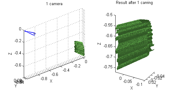
The silhouette is projected onto the voxel array. Any voxels that lie outside the silhouette are carved away, leaving only points inside the model. Using just one camera, we end up with a dinosaur-prism - a single camera provides no information on depth.

voxels = spacecarving.carve( voxels, cameras(1) );

% Show Result
figure('Position',[100 100 600 300]);
subplot(1,2,1)
showscene( cameras(1), voxels );
title( '1 camera' )
subplot(1,2,2)
showsurface( voxels )
title( 'Result after 1 carving' )

Add More Views

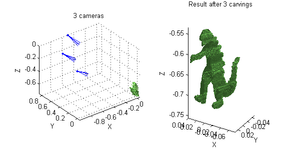
Adding more views refines the shape. If we include two more, we already have something recognisable, albeit a bit "boxy".

voxels = spacecarving.carve( voxels, cameras(4) );
voxels = spacecarving.carve( voxels, cameras(7) );

% Show Result
figure('Position',[100 100 600 300]);
subplot(1,2,1)
title( '3 cameras' )
showscene( cameras([1 4 7]), voxels );
subplot(1,2,2)
showsurface(voxels)
title( 'Result after 3 carvings' )

Now Include All the Views

In this case we have 36 views (roughly every 10 degrees). For a very detailed model and if you have an automatic capture rig you would use far more - the only limit being time and disk-space. When using a computer controlled turn-table (as is done in museums) storage is the only real limitation.

for ii=1:numel(cameras)
    voxels = carve( voxels, cameras(ii) );
end
final_volume = numel( voxels.values );
fprintf( 'Final volume is %d (%d%%)\n', ...
    final_volume, round( 100 * final_volume / starting_volume ) )
Final volume is 168688 (3%)
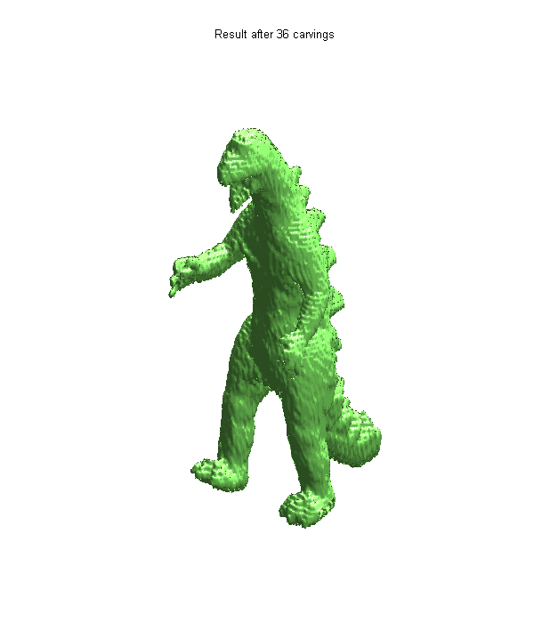
Final Result

For online galleries and the like we would colour each voxel from the image with the best view, leading to a colour 3D model. Maybe one day I'll have time to do that too, but for now here's the uniformly coloured surface.

figure('Position',[100 100 600 700]);
showsurface(voxels)
axis off
title( 'Result after 36 carvings' )

Conclusion

Hopefully this demo has given you a taste for what is possible by simple image masking and space-carving. If this has whetted your appetite, have a look at the references below. Converting each image to a binary mask throws away a lot of information. Instead of using these silhouettes, we could use the image values (either greyscale or colour) and a photo-consistency constraint. This is much harder to get right, but copes much better with concavities and holes in the model.

Have you ever been asked about volume estimation from images? Do you fancy trying this at home? Perhaps you've implemented a better way to do this? I'd love to hear from you here.

File Availability

UPDATE! The functions created for this demo are on the File Exchange. They are available here. As a reminder, there's a link above for getting the data.

References

Some good references for this (including the original paper that used these images) are:

  • Automatic 3D model construction for turn-table sequences, A. W. Fitzgibbon, G. Cross, and A. Zisserman, In 3D Structure from Multiple Images of Large-Scale Environments, Springer LNCS 1506, pages 155--170, 1998
  • A Theory of Shape by Space Carving, K. N. Kutulakos & S. M. Seitz, International Journal of Computer Vision 38(3), 199–218, 2000
  • Foundations of Image Understanding, Chapter 16, edited by L. S. Davis, Kluwer, 2001


Get the MATLAB code

Published with MATLAB® 7.9

36 Responses to “Carving a Dinosaur”

  1. Petter replied on :

    It would be nice if the final shape was texture-mapped with image data from the photos.

  2. michel Kocher replied on :

    Hello, I am refering to your last blog “carving a dinosour”. I was able to locate the data in the provided site but not the spacecarving packag. Could you give some more precise informations.

    Thanks
    Michel

  3. Loren replied on :

    Michel-

    As stated in the post, we will update when the code is available. Thanks for your interest.

    –loren

  4. Anders replied on :

    Hello.

    Im writing a master thesis on a similar subject. I would very much like to try your code and write about its performance. Is it possible to obtain the complete code?

    my mail: anda1293 at student dot uu dot se

    cheers
    Anders

  5. Loren replied on :

    Anders-

    We will update the post when the code is available. Thanks for you interest.

    –Loren

  6. aya alaa replied on :

    i have error on the code is (Undefined function or method ‘loadcameradata’ for
    input arguments of type ‘char’). what i can do

  7. Loren replied on :

    Aya-

    You will have to wait for the code package to get posted. We will update the blog when that’s happened.

    –Loren

  8. John Salari replied on :

    Very interesting! I’m also interested in using it. Although it would be nice if image values could be used to construct the 3D model.

    When is the code package becoming available?

    Cheers, John

  9. Loren replied on :

    John-

    no eta. we’re working on the details so code should be available soon.

    –loren

  10. Ben Tordoff replied on :

    The code is now available here:

    http://www.mathworks.com/matlabcentral/fileexchange/26160

    You’ll have to download the data separately. See the link in the main post.

    Sorry it’s taken so long to get online – thanks for your patience. It does mean I’ve had time to take onboard some of the comments and improve the demo. Find it on the file exchange – you’ll see what I mean.

    Ben

  11. Salma replied on :

    i tried to run the code after adding the octcarve to it

    i have the following error and i picture only displayes and its silhouette

    Error using ==> makevoxels at 10
    Not enough input arguments.

    Error in ==> dinsourprog at 112
    voxels = makevoxels(80 ); % 60 for faster evaluation, 80 for detailed

    what can i do to have the code run correctly?

  12. aya alaa replied on :

    Thank you i try it its fantastic thank you tooooooooo much

  13. Salma replied on :

    Thank you i have tried the code again till it worked but i am thinking about saving the resultant model as .obj not as matlab extensions “fig,emf,..etc.”only to be able to be loaded in 3ds max
    can any one help?

  14. Loren replied on :

    Salma-

    If you are trying to create a stand-alone application, you should look at the MATLAB Compiler and other add-on products for specific targets/environments.

    –Loren

  15. Salma replied on :

    i need to try other images but when i created the file camera matrix created by camera calibration toolbox the resultant file its contents are not as (dino_ps_1.mat)
    I need to know how is it created.

  16. Ben Tordoff replied on :

    Hi Salma, since the .obj format is text-based, it’s possible you could write an exporter. The model created by this demo is a simple patch-based polygonal model and so should be relatively simple to export. I’ve written a basic .obj exporter in the past and don’t remember it being too hard. Alternatively there is the MATLAB command “VRML” which exports a figure as a VRML 2.0 file, if that’s any use to you?

  17. Ben Tordoff replied on :

    Hi Salma, I simply used the projection matrix file provided by the Oxford Robotics Group. I don’t know what software they used to create it – there are a variety of methods and tools out there for estimating projection matrices. Usually these come from estimates of the sequence of fundamental matrices or trifocal tensors. Phil Torr’s “Structure and Motion Toolkit in MATLAB” is a good place to look for this kind of thing. It’s on the file exchange here:

    http://www.mathworks.com/matlabcentral/fileexchange/4576-structure-and-motion-toolkit-in-matlab

    Whichever method you use to get the matrices, you then need to rename and repack them to match the format of the data-file, or, alternatively, change the dinosaur code to match whatever format/naming you have.

  18. richard mullins replied on :

    You asked for comments: “Have you ever been asked about volume estimation from images? Do you fancy trying this at home? Perhaps you’ve implemented a better way to do
    % this? I’d love to hear from you”.

    I had a vacation job (for about 20 days) at Australian Gas Light operations research section in Sydney in 1964.
    One of the jobs I was given was to “estimate the volume of a coke heap”. Each year they would pay a surveyor 1500 pounds (probably as much as $40K in today’s money) to estimate the volume of a coke heap for tax purposes. They wanted to computerise this.

    More recently, I have read of computerised systems to study the shape of gems (for cutting them).
    Also I saw a demo on the net last year, someone took hundreds or thousands of photos inside St Peters in Rome, and a computer system automatically digested this data to produce a (fairly crude) fly-through.

    recently I have been thinking that it would be a good “benchmark” test for a modern CAD system, to see how much work was required (e.g. lines of code) to solve the coke heap problem.

    Yours is the first working demo with source code that I have found.

    Thanks

    richard mullins

  19. Preeti replied on :

    Hello,
    I am trying to implement the same code on the corridor dataset available on the link provided by you. I have generated the matrix explaining the camera positions but I am not able to get the desired result. I need to know how the function findmodel is written and is there any need to change any other function to get the desired result? Figure 3 which represents the camera positions around an object has cameras from only above and below the scene and not in front. According to me there lies the problem. I would appreciate it if you could help me out.

    Thanks,
    -Preeti

  20. Francis Esmonde-White replied on :

    That was a very interesting post. As per the future work commentary: “For online galleries and the like we would colour each voxel from the image with the best view, leading to a colour 3D model. Maybe one day I’ll have time to do that too, but for now here’s the uniformly coloured surface.”

    We’re using 2D images of 3D objects, taken from various perspectives, and then mapping the images back onto the surface of a software model of the object surface. Hence we colour the surface mesh triangles using pixel data which intersects the given triangles. Unfortunately, it’s quite slow at the moment. We’re aligning the 2D images to the mesh manually (using a custom GUI and some landmarks that are common in all the images). The actual colouring is quite fast, but the pixel-to-triangle correspondence mapping isn’t (since we can’t use typical depth-buffered rendering algorithms).

  21. xingming replied on :

    it’s better texture mapping to the final shape

  22. xingming replied on :

    very interesting ,fantastic,i want to do the similar things ,if have the texture mapping to the shape,then it’s perface,thank u tooooooo much

  23. Md Shahnawaz Khan replied on :

    Dear Loren,
    I am a Graduate Student, doing Masters in Artificial Intelligence. I wanted to try your demo but I got the following error :

    cameras =

    1×36 struct array with fields:
    Image
    P
    K
    R
    T
    Silhouette
    rawP

    ??? Undefined function or method ‘montage’ for input arguments of type ‘uint8′.

    Error in ==> space_carving_demo at 67
    montage( cat( 4, cameras.Image ) );

    I am getting this error after downloading the image and data file in the Dinosaurdata folder. Can you please help me in getting it run !

  24. Loren replied on :

    Md-

    As stated in the demo:

    “Note: This demo requires the Image Processing Toolbox.”

    montage is a function in that toolbox.

    –Loren

  25. Shahnawaz replied on :

    Dear Loren,
    After having the Image Processing Toolbox, I am facing the following error. Can you please help ?

    ————————————————–
    ??? Error: File: space_carving_demo.m Line: 197 Column: 11
    Expression or statement is incorrect–possibly unbalanced (, {, or [.

    -------------------------------------------------

    This is how the program- line 196-198 reads :

    for ii=1:numel( cameras )
    [~,mykeep] = carve( myvoxels, cameras(ii) );
    keep(setdiff( 1:num_voxels, mykeep )) = false;

  26. Loren replied on :

    Shahnawaz,

    This demo requires R2009b ( the files you downloaded from then say that ) and you appear to be using a version older than that.

    The version you are using doesn’t allow the use of ~ to ignore output arguments. In addition, there were some changes to the function isosurface as well.

    –Loren

  27. Shahnawaz replied on :

    Dear Loren,
    After making required changes for my old version MATLAB, I was able to run the Demo for Dinosaur. I am keen to try it for my data. I have two questions in my mind :
    1. How do I generate the Camera Matrices file and what is it supposed to contain ? (e.g. the x y z coordinates of the camera,with pinhole camera assumption….what else, please give details )
    2. Do I need to take all 36 images to get an accurate 3D model ?
    (I tried it with four images,without changing the Camera Matrices, naming each of the image in such a way that it took values from camera matrices at 90 degree interval, but i got a very vague model, so I am wondering if images need to be increased or just the camera matrice will do !!)

    Thanks
    Shahnawaz

  28. Shahnawaz replied on :

    Dear Loren,
    After exploring the camera matrices, I found out that my camera needs to be calibrated. So I downloaded the camera calibration tool box from
    http://www.vision.caltech.edu/bouguetj/calib_doc/htmls/updates.html

    From my observations the calibration matrix “K” used for your demo must be containing focal1, skew, focal2 and principal coordinates. If not, please let me know how you extracted your parameters.
    Also the Projection Matrix P in your demo is not equal to :
    K*[R T]
    Please let me know more about the way you used your Projection Matrix P, Calibration Matrix K, Rotation Matrix R and Translational Matrix T.
    Your help is appreciated !

    Shan

  29. Ben replied on :

    Hi Shan,

    I downloaded the P matrices from the owners of the data. You would have to ask the authors exactly how they created them, however I believe they are estimated by tracking image features over the video sequence. Have a look on the Oxford web page linked above to make sure.

    You will see in the code (+spacecarving/decomposeP.m) that I decompose the P matrices into K, R and t. K is not measured from anything physically meaningful, it is simply the result of a matrix decomposition of P. This demo assumes you know P and need to extract K, R and t, not the other way round!

    Cheers

    Ben

  30. Shahnawaz replied on :

    Hi Ben,
    Thanks! I wish if your MATLAB democode had codes to find the Projection Matrix from the Images as well. Though to find the Projection Matrix (or in other words calibrating the external internal parameters) need some information regarding location and size of the object in the real world, one can easily get these information, which, apart from the image, could be taken as an input to the code.

    For us the problem is, even if we calibrate our camera and find the Projection Matrix,but if the convention of chosing the coordinate system varies, the results are different.Can you help me in getting some information from the data providers, for extracting the Projection Matrix from the image using track point from an image sequence. Thanks for your help !

    Shan

  31. Ben replied on :

    Hi Shahnawaz,

    the only thing you need to know is that the object is rotating about a fixed centre (i.e. is on a turntable). That helps when estimating the projection matrices since it reduces the number of degrees of freedom. You do not need to know the camera calibration, the object size or the camera position. These are all deduced (up to scale) from the images. Provided you estimate your P matrices using the same coordinate system as when you use it for reconstruction, no problems should arise.

    The first paper listed in the references at the end of the article is the one that first used this data and it describes how the projection matrices were obtained. It also provides further links if you need more detail. You may also like to get hold of a copy of Hartley & Zisserman’s book “Multiple View Geometry” which provides a thorough description of many of the topics.

    If you really need to contact the original authors, their contact details are in the paper.

    Cheers

    Ben

  32. Ali replied on :

    Hi,

    I’ve been going through your code and trying to understand it and I’m stuck on one part. In the find model function, for finding the zlimit value it is necessary to calculate the direction in which the camera is looking. Could you briefly explain why this has to be done and how the direction is determined?

    A speedy reply would greatly be appreciated!
    Regards.

  33. Ben replied on :

    Hi Ali,

    the camera viewing direction is determined in the function “getcameradirection”. I use this with an estimated “range” to try to work out what the cameras are looking at. This is necessary as the cameras might be looking upwards or downwards (as in the dinosaur data) rather than towards the centre of the ring of cameras. Without it you would probably assume the object is level with the cameras – an assumption that is often wrong.

    Let me know if that explanation is still not clear.

    Ben

  34. Rancho replied on :

    Hi,Ben!
    I’m trying to run your code , substituting a serial of other pictures for dinosaur pictures.
    But get into problems.
    what kind of coordinate system do you use?
    Is it left-handed coordinate system?

  35. Rancho replied on :

    Hi,Ben!
    Can you give me more details about P,K,R and T?
    I’m a student for China.
    I tried to run your code,using other pictures and P matrix,but got problems.
    I think it’s because of different difinition of P,R,K,T matrix.
    Can you help me out?
    Thank you too much!

  36. yuval replied on :

    Loren, this post is out dated, especially the part of

    voxels = makevoxels( 85 )

    Please point to http://www.mathworks.com/matlabcentral/fileexchange/26160-carving-a-dinosaur/content/SpaceCarving/space_carving_demo.m

    in the beginning of the page.


MathWorks
Loren Shure works on design of the MATLAB language at MathWorks. She writes here about once a week on MATLAB programming and related topics.

These postings are the author's and don't necessarily represent the opinions of The MathWorks.