
Signals vs Parameters in Simulink… and the Parameter Writer block
A colleague recently told me that he was often referring users to this blog post I wrote many years ago: How Do I Change a Block Parameter Based on the Output of Another Block?
Even if most of what I wrote in that post still holds today, I thought it would be a good idea to revisit this topic and describe how the Parameter Writer block modifies the game.
Signals vs Parameters in Simulink
In How Do I Change a Block Parameter Based on the Output of Another Block?, I tried to explain something fundamentally different between MATLAB and Simulink. In general, in MATLAB, all the data you create and operate on is stored in variables. You double-click on entries in the Workspace Browser, it opens the Variable Viewer to show the value:

In Simulink there are two types of data:
- Signals: Represented by signal lines in the Simulink canvas, this type of data is expected to potentially change at every time step
- Parameters: Passed to Simulink blocks as MATLAB variables, this type of data is intended to remain constant or changes infrequently.
In many simple cases, the math ends up being the same. For example, using a Sum block to add two signals gives the same results as using a Bias block if its parameter has the same value as the equivalent signal fed to the Sum block. In other words, those 3 are the same:

This raises the question: Why can I not make any block dialog parameter an input signal?
My explanation is that some block algorithms are making assumptions that parameters will change infrequently. Changing those at every time step would lead to results that could be difficult to understand, or completely wrong depending on your assumptions.
In the next two sections, I describe how to tune the value of dialog parameters for situations where this is appropriate, and I give one example where doing it can lead to confusing results.
What if I really want to change the value of a block parameter based on the output of another block?
Since my last post on this topic, we introduced the Parameter Writer block. For a few releases, the Parameter Writer block was restricted to be used only in very specific contexts where the execution order was explicitly defined. In R2023a, we relaxed this constraint and the Parameter Writer block can be used in many contexts. Internally, we analyze the data dependency and make sure the blocks execution order reflects it.
To illustrate how the Parameter Writer block works, I decided to revisit another old blog post: You need an integrator with variable limits… there’s a solution for that!
In this post, I pointed out the fact that the Integrator block has an option to limit its output, but the limits can only be specified as dialog parameters:

At that time, the solution I found to limit the Integrator output using input signals was this complex contraption using the State and Reset ports of the Integrator:

As of MATLAB R2023a, if I am being asked to do the same, I would use two Parameter Writer blocks and bind them to the lower and upper saturation parameters of the Integrator block:

Here is an example model using the above subsystem, changing the integrator limits from +/-10 to +/-1 at t=50sec.

Use at your own risk!
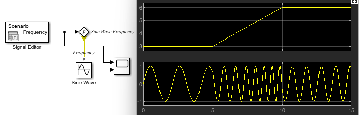
The following is an example I receive every once in a while, where the user wants to progressively change the frequency of a Sine Wave block, let's say from 3 rad/sec to 6 rad/sec over 5 seconds. As you can see, the frequency of the resulting sine wave does not smoothly increase from 3 rad/sec to 6 rad/sec. Instead, it looks twice faster than expected.
Exemplifying what I described above, the Sine Wave block makes the assumption that the frequency is constant. Based on this assumption, instead of integrating the time-varying frequency and computing the angle to be passed to sin:
The Sine Wave block assumes a constant value for ω and implements:
Making ω increase linearly with time () and differentiating the result shows why the resulting function is twice the desired frequency:
To get the desired frequency-increasing sine wave, you want to integrate the time-varying frequency:

Another tip here... if you implement this model, I recommend enabling the Wrap State option of the Integrator block. This will avoid its output to grow infinitely as the simulation time increases, which could lead to numerical issues for long simulations:

Because of these types of subtleties, I recommend using the Parameter Writer block only in contexts where it is executed only infrequently. This could be for example in a Triggered Subsystem, Function-Call Subsystem, Initialize Function, etc.
Now it's your turn
Are you a fan of the Parameter Writer block? Do you have challenges with this concept of "Signal vs Parameters" in Simulink? Let us know in the comments below.


コメント
コメントを残すには、ここ をクリックして MathWorks アカウントにサインインするか新しい MathWorks アカウントを作成します。