An Ounce of Design Min/Max is Worth…
Often, it is worth putting a bit of extra effort at the beginning of a project to save time later.
Today I want to introduce a feature that gets more useful with every release of Simulink, but unfortunately I think very few people use it: Signal Ranges
How do Signal Ranges work?
In Simulink, there are many places where you can specify design ranges:
- Many block outputs
- Some block parameters
- Data objects, like Simulink.Parameter and Simulink.Signal.
- Bus Elements
For example, let's consider a model where I know the controller should generate a voltage between -12 and 12 volts:

In the dialog of the block generating this signal, I can specify this range:
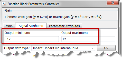
Debugging is made easier with design ranges
Once design ranges are defined in your model you can use the diagnostic Simulation range checking to identify signals that are outside the expected range.
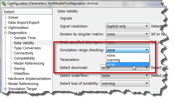
If a signal exceeds its design range, you will receive an error pointing to the problematic block.
Note: This diagnostic performs range checking at every time step during a simulation. Setting it to warning or error adds work to your simulation, and can cause a decrease in simulation performance... so use it only when needed.
Collaborative workflows are easier with design ranges
If you are developing a model with other engineers, specifying the ranges of your signal will help everyone to understand your algorithms.
From the Display menu, you can enable the display of Signal Ranges:
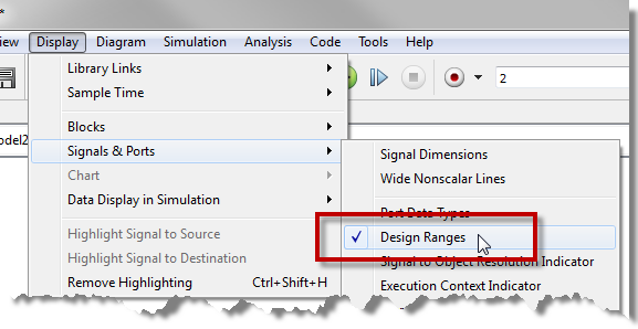
Here is how it looks like in the model:

Fixed-Point Data Types
Min/max values are useful to explicitly specify fixed point data types. After you specified the range, open the data type assistant and start specifying a fixed-point type. If you know the min/max value, Simulink can compute the best fraction length or slope/bias for you.
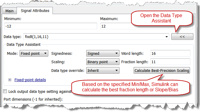
Now it's your turn
Let us know how you use the design ranges in your models by leaving a comment here.




评论
要发表评论,请点击 此处 登录到您的 MathWorks 帐户或创建一个新帐户。