Hyperloop Model Architecture: We want your feedback!
We had some fun in our last post about the Hyperloop open source transportation system, but we didn't get much into the specifics. This week we begin to move things forward.
Before beginning to analyze the feasibility of individual components, we decided to think about how we would architect a Simulink model to simulate the Hyperloop. In my opinion, such a model should include:
- Componentization: It must be possible for a component to be used in isolation in test models, or as part of full system model
- Variants: For each component, it must be easy to switch between different levels of fidelity or content.
- Intuitive: If many engineers are going to participate in this project, it must be easy for them to understand the model.
With that in mind, Matt and I (Guy) built tentative architectures which we describe today. If you have experience creating models for collaborative development involving multiple engineers, we would really like to hear what you think in the comments.
Matt: Systems Approach
I really liked the way the hyperloop proposal partitioned the different systems. So, I followed their lead in my model architecture. I put six systems at the top level. Where applicable, the controls for that specific system reside with its model. This choice makes componentization more straight forward. I like to put images on a mask for each system to make their content clear.
Each of these systems contains a referenced model. Those models become stand-alone environments for contributors to develop their own solutions for that system. Theoretically, these solutions could even depart from those put forth in the proposal. The developer is also free to utilize the modeling domain of their choice, be it Simulink, Simscape or integration of external tools.
It is possible to integrate different combinations of solutions and see how they work together. Variant selection can be parameterized as shown in the Block Parameter dialog below. Here, the variable varComp determines the active variant for the Compressor system.

The valid combinations could be managed through configuration sets within the Variant Manager. In the example below, there is a configuration for a Simulink version of the hyperloop proposal, a Simscape version of the same and a third configuration that utilizes a more conventional solution with hub motors and an independent suspension.

Since the interfaces between my components use Simulink signals, any toolbox or third party tool can be used to design the components. We can leverage advanced physical modeling tools and all users can reap the benefits.
From my perspective, the system-based hierarchy, combined with the images, makes an intuitive model. Using Model Reference means that there is a mechanism for variant control. Using Model Referencing with the right elements of the hierarchy provides the final ingredient; componentization. It’s all there.
Guy: Plant-Controller
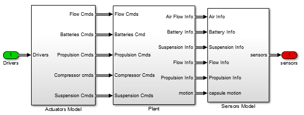
To begin, I decided to go with an architecture I see often in Model-Based Design projects: a plant and a controller.

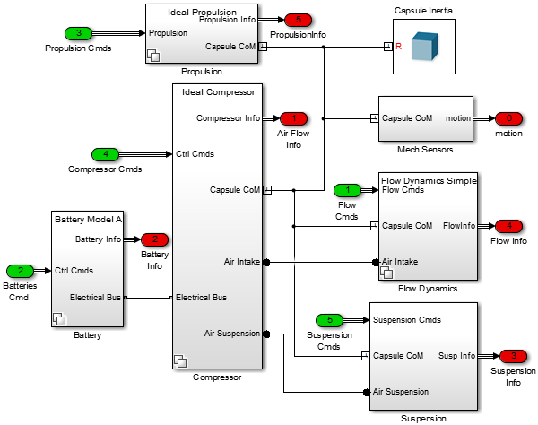
If you look inside the plant, you can find a layer where I convert signals between the ideal continuous plant and the discrete fixed-step controllers.

In the actual plant subsystem, you can see that I make intensive usage of our physical modeling toolboxes. I centered the design around one SimMechanics Solid block representing the center of mass of the capsule.

I also think we should use the Simscape electrical and pneumatic domains to model interactions between components.
To help identifying the data flow, I like to use a color code: green for Inports, red for Outports, blue for SimMechanics connections, etc...
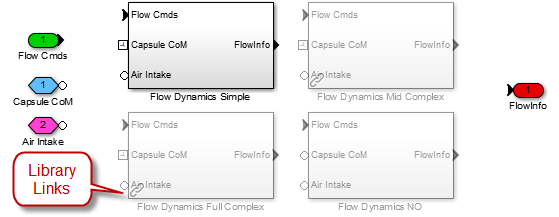
Each component is a Variant Subsystem containing multiple versions of the component, with different implementations. The variants are stored in separate library files. By using a "one file per variant" approach, individual developers should be able to work in their own library file without modifying the rest of the model. This will also allow them to test their designs in smaller test models if needed.

With the central SimMechanics connection, each component can connect to the capsule to get information about its dynamics and apply forces or constraints to it. For example, the simplest model of air drag could look like the following, where I use a Transform Sensor to measure the capsule forward velocity and an External Force and Torque block to apply the drag.

For convenience, I packaged all my files in a Simulink Project. The startup script automatically sets the path and creates necessary variables as you open the project. I also defined shortcuts for common tasks, like opening the main model and plotting the final trajectory.

Now it’s your turn
As you can see, our architectures are very different. We would really like to hear what you think. Do you prefer one, or the other, or something completely different? Tell us why by leaving a comment here.


コメント
コメントを残すには、ここ をクリックして MathWorks アカウントにサインインするか新しい MathWorks アカウントを作成します。