Simulating the Startup and Shutdown of your software
This week, we are finally diving into the Initialize Function, Reset Function and Terminate Function blocks.
As a starting point, I recommend looking at this video about Initialize and Terminate Functions by my colleague Teresa Hubscher-Younger.
Simulating the Startup and Shutdown of the Generated Code
In this previous post about Export Function models, we have seen how we can simulate a model configured to export functions: by referencing it using a Model block.
In this example, we were able to simulate the behavior of the code being run once. In other words, if the code will be running on an embedded controller unit (ECU), what this model simulates is that the ECU boots up when the simulation starts, the code runs, and the ECU shuts down when the simulation terminates.
This is interesting, but what if you want to simulate a larger scenario, where the ECU is booted up and shut down multiple times? This is what the Initialize Function and Terminate Function are designed for.
What Teresa's example does is simulating a car being started and shut down multiple times, due to two different conditions. When the car is running, we are incrementing a counter to keep track of how long the engine has been running, in its entire life. In a normal shutdown case, when the key is turned off, we need to write the total run time in a non-volatile memory, so it can be retrieved next time the car is started. In case the battery dies, the car also shuts down, however in that case we don't have time to write to the non-volatile memory.
Let's see how to make that happen!
Enabling Initialize and Terminate Events
Let's begin with a simple export-function model implementing a counter.

In R2016b, you will notice that when you reference a model setup to export functions, the dialog of the Model block includes two new options.

When you enable those, the model block will show two new ports, to which you can connect function-call signals. As a first simple test, let's make a Stateflow chart to start and shut down our counter when the key is turned on or off:
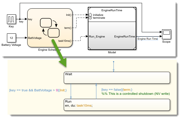
If we look at the results, we can see that the counter increments when the key is on, and stops when it is off. When the key passes from off to on, the counter gets reset.

Custom Initialization and Terminate Events
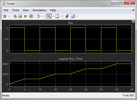
As described earlier, we do not want the counter to reset at every shutdown. To keep the counter value, we can use Intialize Function and Terminate Function blocks. Inside the Terminate Function, we use the State Reader block to obtain the current counter value and store it into a Data Store block. Similarly, inside the Initialize Function, we will read the Data Store block and use it to initialize the counter.

Now when we look at the results, the counter keeps increasing after being shut down and restarted.
Reset Function
As mentioned previously, we also need to handle the case where the vehicle shuts down because of low battery voltage. This means that we do not want to write to the Data Store every time the model terminates.
To do that, we can change Event Type in the Terminate Event Listener block from Terminate to Reset and give it a meaningful name. In that case, since the model does not have a Terminate Function block anymore, the default blocks terminate function will be executed when the simulation harness will trigger the terminate event.

We update the Stateflow Scheduler to cover both shutdown cases:
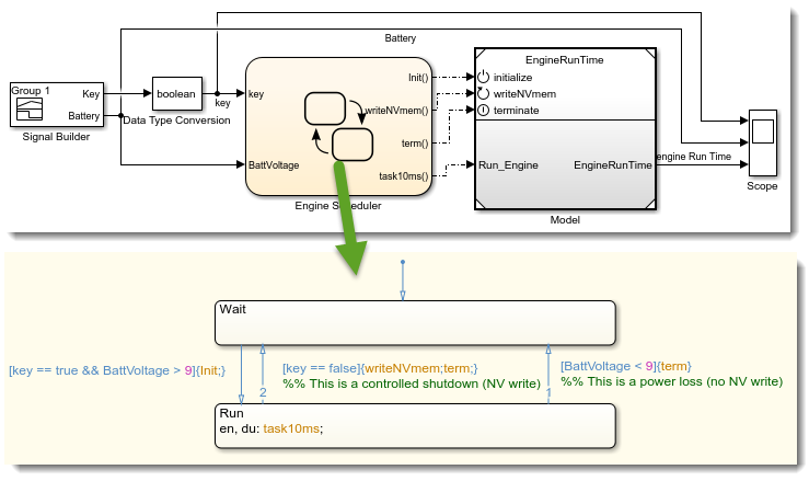
Note that in the above model, in the Model reference parameter dialog, we enabled the "Show model reset port(s) option". This is what gives us the additional writeNVmem port.
When looking at the results, we can now see that if the shutdown is caused by a battery failure, the counter value is not kept for the next restart.

Code Generation
Now that we have a simulation that behaves as expected, let's look at configuring code generation.
In the generated code, writing to the non-volatile memory very likely needs to be done using custom code or hardware services provided by the embedded target. To deal with that, we will use Function Caller blocks and Simulink Functions in the way highlighted in this previous post.
To resume in a few words, we replace the Data Store blocks by Function Caller blocks in the export-function model. To get the simulation behavior, we use Simulink Functions implementing the same logic as previously done in the Initialize and Terminate Functions, reading and writing to data store blocks.
Here is what the overal contraption looks like:
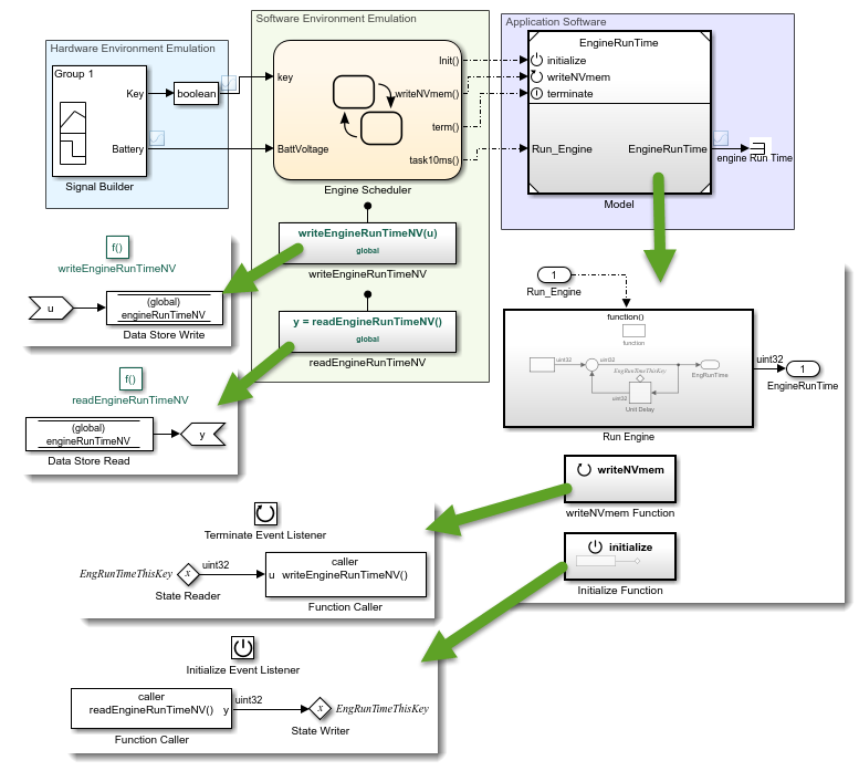
As described in this previous post, for code generation, it is possible to specify in the configuration of the export-functions model where the functions writeEngineRunTimeNV and readEngineRunTimeNV should be found at linking time.
If we generate code for the Export Function model, what we get looks like:

Now it's your turn
Let us know what you think of this semantics by leaving a comment below.




评论
要发表评论,请点击 此处 登录到您的 MathWorks 帐户或创建一个新帐户。