Modeling flexible bodies using the Reduced Order Flexible Solid block
Today I am happy to welcome guest blogger David Balbuena. If you are getting started using the Reduced Order Flexible Solid block from Simscape Multibody, I strongly recommend that you go through David's MATLAB Central contribution. Whether you are importing your reduced-order model from the Partial Differential Equation Toolbox or any other third-party finite-element analysis software, this should help you avoid common mistakes and get you running quickly.
---Guy
In this post, I am introducing a MATLAB Central submission to help you validate your workflow for generating the data required by the Reduced Order Flexible Solid block.
Before diving in, let’s review the evolution of flexible bodies in Simscape Multibody.
Evolution of Flexible Bodies in Simscape Multibody
Prior to R2018b, Simscape Multibody did not include built-in blocks to model flexible bodies. In those days, you had to use a series of rigid bodies connected by springs and dampers, as Guy demonstrated in a previous post. Since then, we've added lots of new capabilities for modeling flexible bodies! Here's a quick summary:
| Release | Block | Description | Image |
|---|---|---|---|
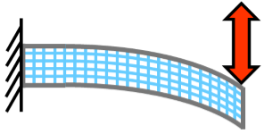
| R2018b | General Flexible Beam | Flexible beams with a constant cross-section | 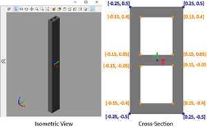 |
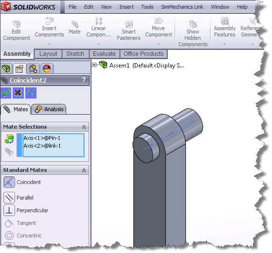
| R2019b | Reduced Order Flexible Solid | You can start with the CAD geometry of your component, generate a finite-element mesh, apply the Craig-Bampton FEA substructuring method, and generate a reduced-order model | 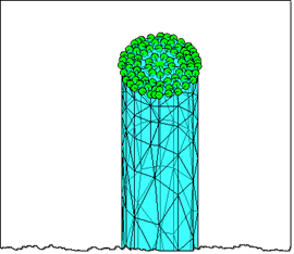 |
| R2020a | Flexible Beams with standard cross sections | Standard flexible beams added to the library |  |
Now you can easily build and simulate cool stuff like this flexible four bar mechanism:

Reduced Order Flexible Body
The Reduced Order Flexible Solid block is different from the other flexible beams because it can use data generated from FEA software. It requires a reduced-order model (ROM), which you can get by taking the CAD geometry of your component, generating a finite-element mesh, applying the Craig-Bampton FEA substructuring method, and then generating a reduced-order model.
The nature of this block comes with a challenge: since it uses data from a third-party software, it is impossible for us (MathWorks) to check that the data you provide actually represents what you intend.
Once you have the ROM, you can enter the data generated in the Simscape Multibody block along with the CAD part:

The ROM data primarily consists of 3 matrices
- A matrix of Interface Frame Origins
- Stiffness Matrix
- Mass Matrix
The documentation lists out requirements for the ROM. It is important to keep those in mind if you need to manipulate the ROM data. One thing to be aware of is this line in the documentation:
The degrees of freedom for node i must be retained in the order Ui = [Txi, Tyi, Tzi, Rxi, Ryi, Rzi]
It's also important to note that the boundary nodes in the reduced-order model must be in the same order as the corresponding interface frames on the block. If your third-party software generates the interface frames in a different order, you will need to reorder the stiffness and mass matrices to account for that difference.
So, let's say you generated your ROM data, and you need to change the ordering of your frames. Assuming you have only 2 frames, and no dynamic modes, then your $U$ vector becomes:
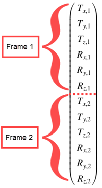
And your origins matrix will match that ordering:

With that ordering comes a natural structure on your stiffness and mass matrices. In this case you can think about the stiffness matrix (K) as a 2x2 partitioned matrix:

The mass matrix will have the same structure.
With the pictures above in mind, now we can swap the two frames. That is equivalent to swapping the first 6 rows with the last 6 rows of $U$. For the origins matrix you can simply swap the rows:

To correctly modify the stiffness and mass matrices, you need to permute the rows AND columns. Below is a visualization for the change you have to make to the stiffness matrix. The first partition is highlighted for clarity.

You would need to do the same thing for the mass matrix. This ensures that changing the ordering of your frames maintains the correct degrees of freedom for each frame.
Troubleshooting
When importing the ROM, the Reduced Order Flexible Body block does some validation of the matrices you provide. If it detects something suspicious, the following warning will be thrown:
The provided reduced-order model data (mass matrix, stiffness matrix, interface frame origins) do not appear to correctly characterize the rigid-body properties of the flexible body. Check that the provided data is correct and consistent. Resolve this issue in order to remove the warning.
If you are getting the warning above, keep reading, because the following steps will help you validate your ROM generation process. To do that, I like to use a simple shape because with a simple shape it is easy to see how the settings you choose in your FEA software translate into Simscape Multibody.
File Exchange Setup
I decided to use a simple system with a known solution: a cantilever beam with a circular cross section. You can go to your FEA software of choice and generate a ROM for a cylinder with these properties:
- Radius: r = 0.05 m
- Length: L = 1 m
- Density: ρ = 2700 kg/m^3
- Young's Modulus: E = 70 GPa
- Poisson ratio: 0.33
- 2 interface frames, one at each end
Here is a picture of such a cylinder meshed using the Partial Differential Equation Toolbox. You should see something similar if you implement this cylinder in a different FEA software.

For a beam with those properties, you can calculate by hand how it should respond to different loading conditions. The following sections walk through some basic tests I typically run:
Tension
If you apply a force $F$ along the axis of the beam, you should get a steady state deformation of$$\Delta L = \frac{F \cdot L}{A \cdot E}$$
where $A$ is the cross-sectional area of the beam, $E$ is the Young's Modulus, $L$ is the length of the beam.
Torsion
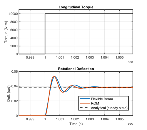
If you load the beam in torsion with some torque $T$, you should get a steady state twist angle of
$$\theta = \frac{T \cdot L}{G \cdot I_P}$$
where $G$ is the shear modulus, $I_p$ is the polar moment of inertia.
Bending
If you apply a pulse to the end of the beam in a direction perpendicular to the axis of the beam, you should get a response that oscillates at the first natural frequency of the beam
$$\omega_1 = 1.87510^2 \sqrt{\frac{E \cdot I }{\rho \cdot A}} = 447.6 \frac{rad}{s}$$
where $I$ is the moment of inertia, $\rho$ is density, $A$ is cross sectional area, $E$ is Young's Modulus.
Validating ROM Results
Now we know how the beam should respond. In my MATLAB Central submission, there is a model that replicates the loading conditions above and compares the simulated response to the analytical solution we calculated:

All you have to do is enter your ROM data in the model. The default data provided was generated using the reduce function in the Partial Differential Equation Toolbox. If you are interested in how I did that, the submission contains the code I wrote to do it. The Simulink model provided compares the ROM response to a Flexible Cylindrical Beam. The links on the model canvas will open up plots so you can explore the results:
See the README file for more details on how the model is setup.
Now it's your turn
Here are a few more resources to get you started:
- Flexible Dipper Example
- Use PDE Toolbox to generate a ROM for the dipper arm
- MATLAB Central submission
- Reduced Order Model Requirements
Try out the Reduced Order Flexible Solid block and let us know what you think in the comments below.





评论
要发表评论,请点击 此处 登录到您的 MathWorks 帐户或创建一个新帐户。