
Configuring a Simulink Model for AUTOSAR
Today I am happy to welcome guest blogger Sai Ram Anumula to give an introduction on how to configure Simulink models to generate AUTOSAR compliant code.
Some time ago, my colleague Shwetha published a Introduction to AUTOSAR post, where she gave a overview of the AUTOSAR Standard and the capabilities of the Simulink AUTOSAR Blockset to develop AUTOSAR Classic applications. Today, we will step through the details of translating, or converting, a simple Simulink model into an AUTOSAR model to generate AUTOSAR compliant code.
For this process of translation or conversion, AUTOSAR Blockset can do the magic for you in two ways:
- Top-down workflow: You start with a software component or composition descriptions stored in an AUTOSAR XML files and import it as Simulink AUTOSAR components/composition models or architecture models.
- Bottom-up workflow: You start with a Simulink model or an architecture model (implemented using System Composer, see this example), configure it for AUTOSAR and then export ARXML files to be used in the rest of your AUTOSAR toolchain.
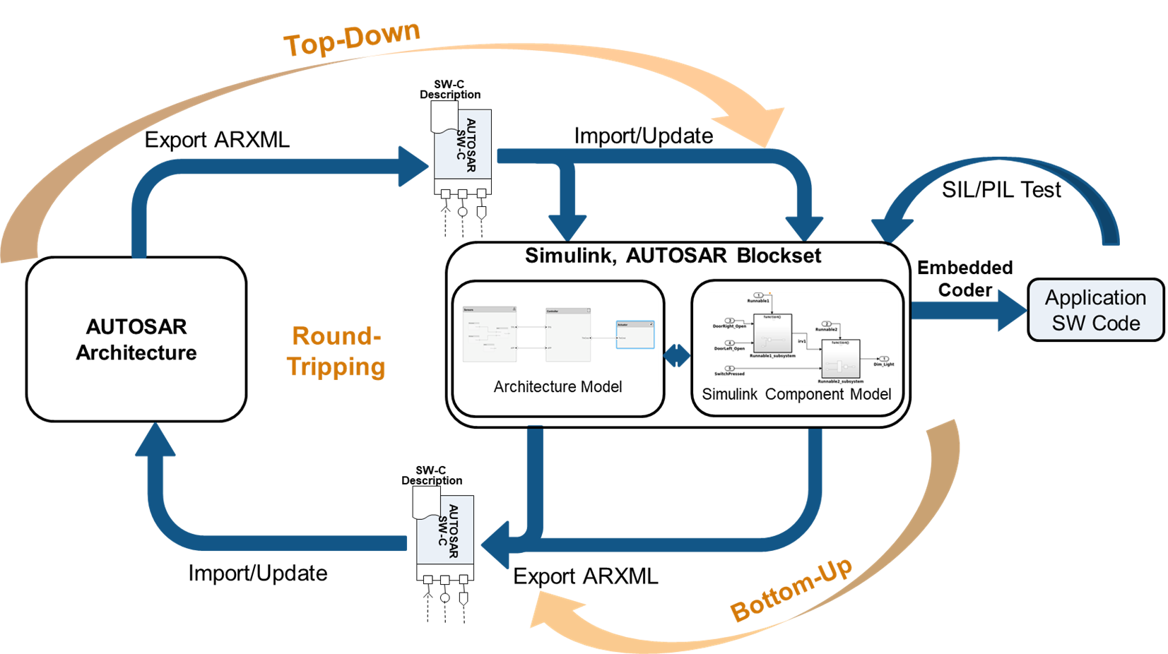
In this post, we are demonstrating the bottom-up workflow.
Quick start using AUTOSAR Component Designer
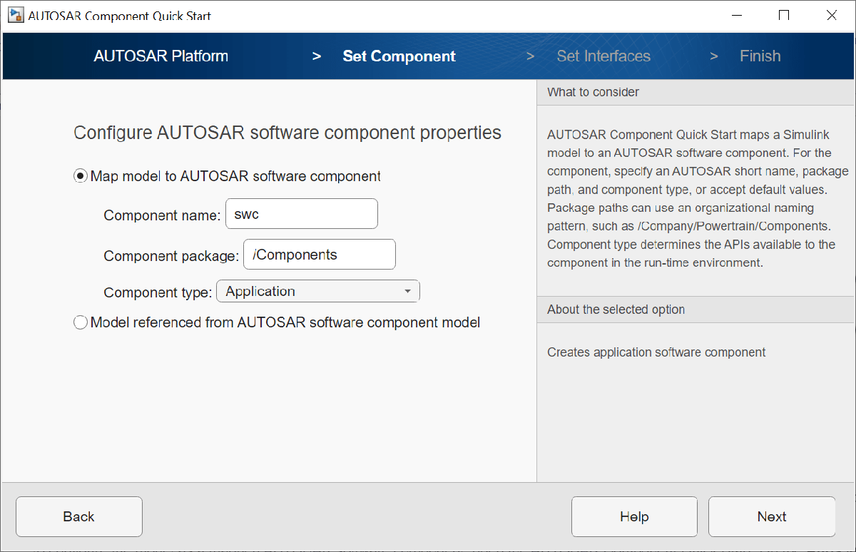
To begin, you can start by opening the AUTOSAR Component Designer App and follow the steps to map your Simulink model to an AUTOSAR Software Component. Here is a short animation going through those steps:

Once all the options are configured in the Quick Start menu, the Code Mappings Editor and Property Inspector will open, providing an AUTOSAR perspective of the model and allowing you to further configure the Software Component.
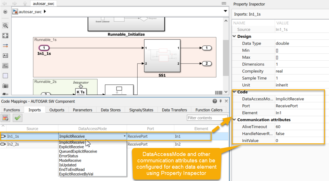
Configuring Simulink-AUTOSAR Code Mappings
The Code Mappings Editor helps to configure the model as an AUTOSAR Software Component. Here is a list of mappings between Simulink features and AUTOSAR elements:
- Entry-point functions <-> AUTOSAR runnables
- Inports and Outports <-> AUTOSAR Sender-Receiver Ports
- Model Workspace Parameters <-> AUTOSAR Component Parameters
- Data Stores <-> AUTOSAR variables
- Block Signals/States <-> AUTOSAR variables
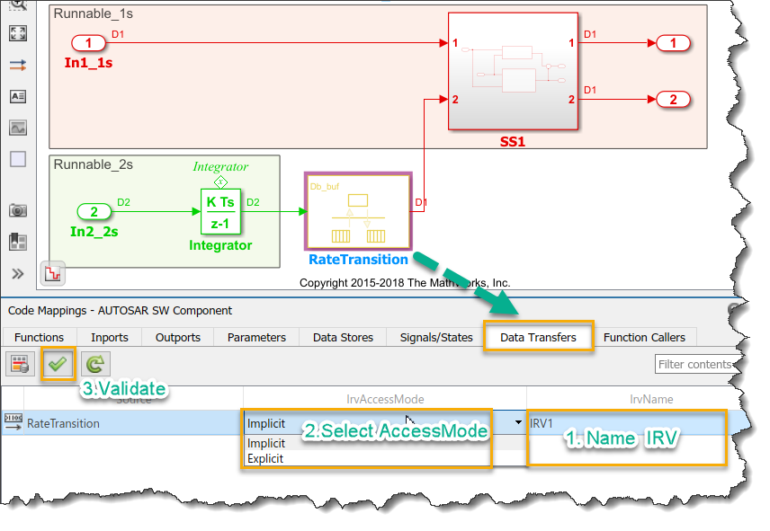
- Data Transfers <-> AUTOSAR Inter-Runnable Variables
- Function Callers <-> AUTOSAR Client-Server Ports and Operations
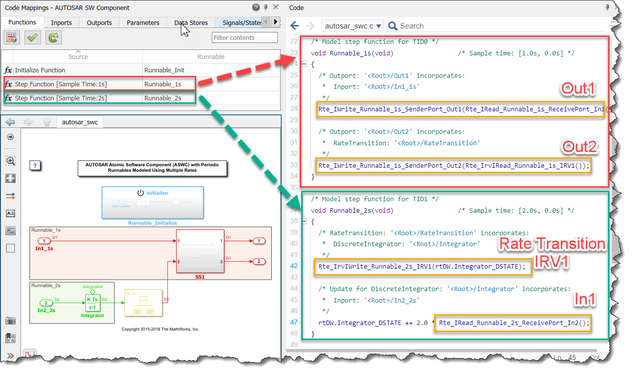
Here is an example showing a Rate Transition block being mapped to an implicit Inter-Runnable Variable:
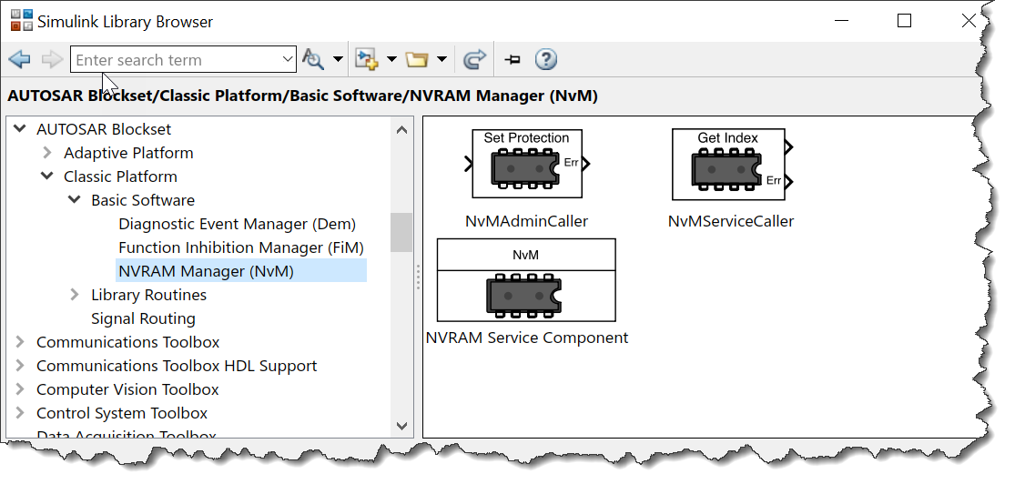
Further you can leverage the blocks corresponding to Basic Software Services which are readily configured for you as per the AUTOSAR standard for code generation and emulation of these services. For example, You may use NvMServiceCaller block to call the AUTOSAR NvM service interface and generate code out of it. You can also use NVRAM Service Component block to emulate the AUTOSAR NvM service calls in a system-level and composition-levels simulations.
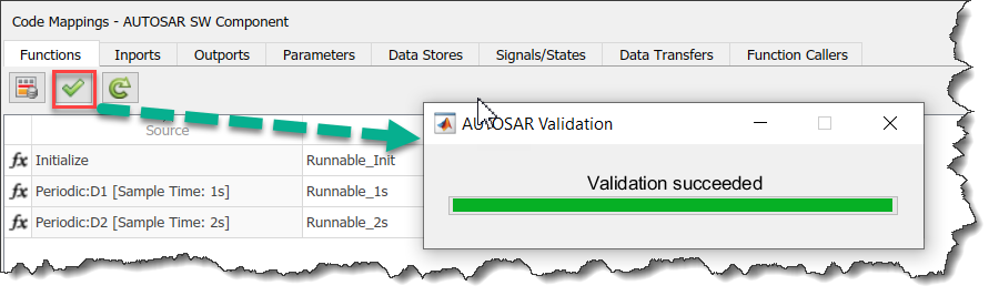
Once you have a Software Component fully developed, it’s time to validate the AUTOSAR properties and mappings before attempting code generation:
Inspecting generated AUTOSAR Code
Upon successful validation, you can generate code and inspect the C code and XML software descriptions to confirm that they comply with the AUTOSAR specification:
Now it's your turn
Explore the AUTOSAR Blockset landing page to learn more how it could help you generating an AUTOSAR compliant C/C++ code from Simulink models in just a few steps.
If you have the blockset installed, I recommend going through the various examples located here.
- Category:
- AUTOSAR,
- Code Generation,
- What's new?


See Also
-

Introduction to AUTOSAR
Blogs

Comments
To leave a comment, please click here to sign in to your MathWorks Account or create a new one.