
Understanding the C/C++ Code Generated from a Simulink model
One of the key benefits of Simulink is that you can generate C/C++ code from the model using Simulink Coder and Embedded Coder.
However, I have to admit, looking at the code generated from Simulink for the first time can be intimidating. In this post, I will try to demystify that a little bit.
The Challenge
The first time you generate code from a Simulink model, you notice that a folder gets created with multiple files in it. If you open one of them, for example "modelname.c", you will see something like this:
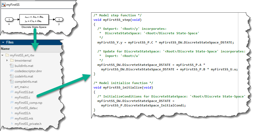
This probably raises a lot of questions: What are all those functions and variables? Where do they come from? Is there a naming convention? Can I control how the variables are named? How do the equations in the C code relate to the blocks and signals in my Simulink model?
To help answer those questions, this post goes through the following:
- The Simulation Loop: To understand the code generated from Simulink, it's important understand how Simulink models are simulated
- Generated Code - Data Structures: How the block parameters, states, and signals are organized in the generated code
- Generated Code - Optimization: Why the code is usually not a 1-to-1 mapping with the blocks and signals in the model
- Generated Code - Customization: Get full control of the variables and data structures in the generated code
Let's get started!
The Simulation Loop
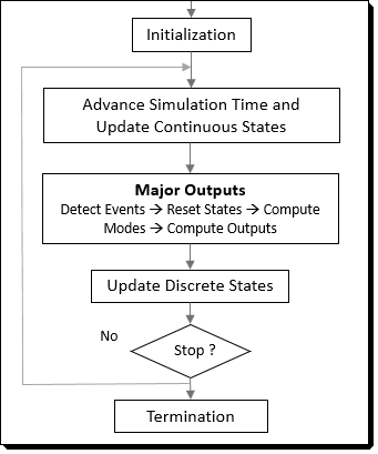
To understand the code generated from Simulink, you first need to understand how Simulink solves the equations implemented as blocks in a model. For that, I like to use a simplified version of the diagram from this documentation page: Simulation Phases in Dynamic Systems - MATLAB & Simulink.
Obviously, this diagram is a simplification of what Simulink actually does. To get the full picture, I recommend this page: Simulink Engine Interaction with C S-Functions - MATLAB & Simulink.
For models without continuous states (this is true for most code generation use cases where the user cares about the generated code), the equations for all blocks are solved in two groups:
- Output: Simulink computes the output of all blocks as a function of their current inputs and states.
- Update Discrete States: Simulink computes the value of the states for the next step, as a function of the block inputs and current states.
Now, let's look at a specific example.
Example: Discrete State-Space
In my opinion, the best classic example to illustrate the basics of how Simulink works is a Discrete State-Space system (State-space representation - Wikipedia). It results in one equation for the Output phase and one equation for the Update phase.
While Simulink includes a Discrete State-Space block, for the purpose of this blog post, I decided to implement it as typically seen in controls or dynamic systems books:
mdl = "testCG";
open_system(mdl)
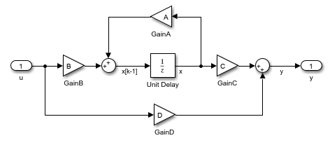
This gives two equations:
- Output:
- Update Discrete States:
The Generated Code
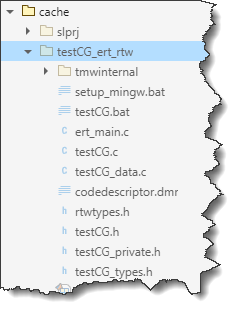
If you generate code for the above model, you will see a folder like this being generated:
slbuild("testCG");
Functions
With the default settings (minus the comments), Simulink Coder produces three functions in testCG.c: initialize, step, and terminate:
void testCG_initialize(void)
{
testCG_DW.UnitDelay_DSTATE = testCG_P.UnitDelay_InitialCondition;
}
void testCG_step(void)
{
testCG_Y.y = testCG_P.C * testCG_DW.UnitDelay_DSTATE + testCG_P.D * testCG_U.u;
testCG_DW.UnitDelay_DSTATE = testCG_P.A * testCG_DW.UnitDelay_DSTATE + testCG_P.B * testCG_U.u;
}
void testCG_terminate(void)
{
}
Most users prefer to see the Output and Update phases described above combined into a single function, so Simulink Coder combines them into a single Step function. There are options to control this behavior if desired.
Data Structures
To understand this code, let's look at how the data is organized. In most code generated from Simulink, you will find 4 data structures:
- Inputs ("U"): a structure with one field per Inport
- Outputs ("Y"): a structure with one field per Outport
- Parameters ("P"): a structure with one field per parameter
- States ("DW"): a structure with one field per state. (DW stands for Discrete Work vector)
Knowing that, we can find their declaration in the generated header file (testCG.h):
typedef struct {
real_T u; /* '<Root>/u' */
} ExtU_testCG_T;
typedef struct {
real_T y; /* '<Root>/y' */
} ExtY_testCG_T;
struct P_testCG_T_ {
real_T A; /* Variable: A */
real_T B; /* Variable: B */
real_T C; /* Variable: C */
real_T D; /* Variable: D */
real_T UnitDelay_InitialCondition; /* Expression: 0 */
};
typedef struct {
real_T UnitDelay_DSTATE; /* '<Root>/Unit Delay' */
} DW_testCG_T;
The values for block parameters are specified in the data file (testCG_data.c),:
/* Block parameters */
P_testCG_T testCG_P = {
/* Variable: A */
0.95,
/* Variable: B */
0.25,
/* Variable: C */
0.2,
/* Variable: D */
0.0,
/* Expression: 0 */
0.0
};
For the initial state, the value is set in the initialize function (testCG.c)
/* Model initialize function */
void testCG_initialize(void)
{
testCG_DW.UnitDelay_DSTATE = testCG_P.UnitDelay_InitialCondition;
}
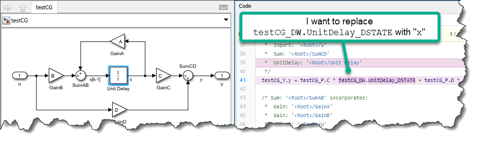
To observe the relationship between the blocks in the model and the generated code, I recommend opening the Code Panel. This feature enables bi-directional highlighting: you can hover over parts the code and the corresponding blocks get highlighted, or you can click on blocks in the canvas and the corresponding code gets highlighted:
A little bit more about block parameters
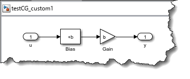
While inputs, outputs, and states map to individual modeling elements, parameters can be used in multiple blocks, and this is reflected in the generated code. Let's take this simple example where I use a variable "b" in both the Bias and Gain block:
The comments in the data file (testCG_custom1_data.c) indicates that the same C code variable is used by two blocks:
/* Block parameters (default storage) */
P_testCG_custom1_T testCG_custom1_P = {
/* Variable: b
* Referenced by:
* '<Root>/Bias'
* '<Root>/Gain'
*/
2.0
};
In the equation for the step function, we can confirm that the same variable "testCG_custom1_P.b" is used for both the bias and the gain:
void testCG_custom1_step(void)
{
testCG_custom1_Y.y = (testCG_custom1_U.u + testCG_custom1_P.b) * testCG_custom1_P.b;
}
Optimization
At this point, you might be wondering:
You said that Simulink computes the output and states of each block. The model has 10 blocks, and I only see two equations, what happened?
The answer is simple: By default, Simulink Coder optimizes the generated code!
Simulink has tons of optimization settings that I will not cover in detail here. Personally, the most frequent reason I have to disable optimizations is debugging, to inspect intermediary variables more easily.
This can easily be set in the model configuration:
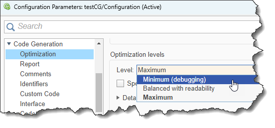
Programmatically, this can be done using:
set_param("testCG","OptimizationLevel","level0");
And we now get one line of code per block:
void testCG_step(void)
{
/* UnitDelay: '<Root>/Unit Delay' */
testCG_B.x = testCG_DW.UnitDelay_DSTATE;
/* Gain: '<Root>/GainC' */
testCG_B.GainC = testCG_P.C * testCG_B.x;
/* Gain: '<Root>/GainD' */
testCG_B.GainD = testCG_P.D * testCG_U.u;
/* Outport: '<Root>/y' */
testCG_Y.y = testCG_B.GainC + testCG_B.GainD;
/* Gain: '<Root>/GainA' */
testCG_B.GainA = testCG_P.A * testCG_B.x;
/* Gain: '<Root>/GainB' */
testCG_B.GainB = testCG_P.B * testCG_U.u;
/* Sum: '<Root>/SumAB' */
testCG_B.xk1 = testCG_B.GainA + testCG_B.GainB;
/* Update for UnitDelay: '<Root>/Unit Delay' */
testCG_DW.UnitDelay_DSTATE = testCG_B.xk1;
}
As you can see, this introduces a new data structure ("B"), containing the output of the individual blocks.
Don't forget to switch back the optimization level to maximum when you're done debugging!
set_param("testCG","OptimizationLevel","level2");
Customization
In many cases, you don't need and don't want to customize the generated code. In fact, if you generate code for Rapid Prototyping or Hardware-In-the-Loop simulation, you probably don't even need or want to look at the generated code!
However, in some cases, you might have a good reason for wanting to customize the generated code. Good news, with Embedded Coder, it is possible to customize almost everything in the generated code.
One common and simple use case is the need to interface with hand-written code. For that, you want to tell Simulink Coder that a specific modeling element should become a specific variable in the generated code. Let's look at two examples of that.
Customization 1: Exporting a State
Let's say that we want the generated code to read and write the state of the Unit Delay block in our state-spate system to a variable named "x" that the hand-written code will be able to access.
Customization 2: Exporting a Signal
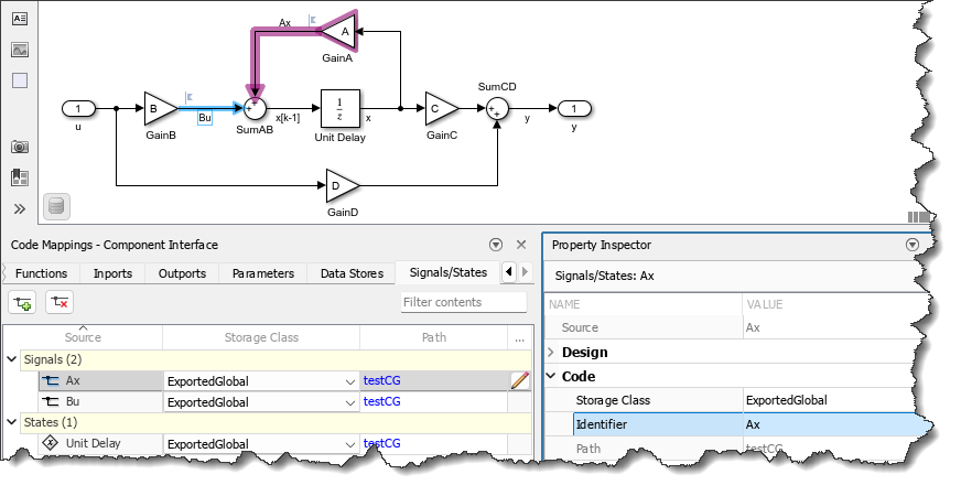
As discussed in this previous post, another common customization is to retain a specific signal in the generated code. For our state-space example, let's say we want to be able to access "A*x" and "B*u":
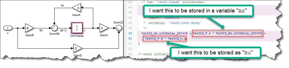
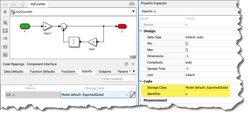
To implement those two customization, you can use the Code Mapping Editor. Go to the Signals/States tab, and change the Storage Class of the state of the Unit Delay block and of the two signals Ax and Bu to ExportedGlobal. In the Property Inspector, you can specify the Identifier you want to appear in the generated code:
With that change, the generated code becomes:
void testCG_step(void)
{
testCG_Y.y = testCG_P.C * x + testCG_P.D * testCG_U.u;
Ax = testCG_P.A * x;
Bu = testCG_P.B * testCG_U.u;
x = Ax + Bu;
}
When generating code for the simple examples I publish on this blog, I like to abuse this capability a little bit. With a few more clicks in the Code Mapping Editor, I can turn the generated code into this:
void testCG_step(void)
{
y = C * x + D * u;
x = A * x + B * u;
}
You probably don't want to go that extreme for the code generated for your application!
Now it's your turn
I think it's enough for an intro to the C/C++ code generated from Simulink Coder. Let us know in the comments below if there are other code generation related topics you would like to see covered on this blog.
- 범주:
- Code Generation


댓글
댓글을 남기려면 링크 를 클릭하여 MathWorks 계정에 로그인하거나 계정을 새로 만드십시오.